Firmware Upgrades
Before we discuss firmware upgrades, one pertinent topic that needs to be discussed is the flash partitions.
Flash Partitions
The ESP-IDF framework divides the flash into multiple logical partitions for storing various components. The typical way this is done is shown in the figure.
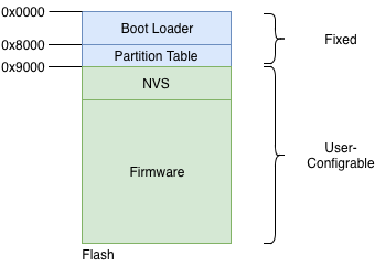
Flash Partitions Structure
As can be seen, the structure is static upto flash address 0x9000. The first part of the flash contains the second-stage bootloader, which is immediately followed by the partition table. The partition table then stores how the rest of the flash should be interpreted. Typically an installation will have at-least 1 NVS partition and 1 firmware partition.
OTA Mechanism
For firmware upgrades, an active-passive partition scheme is used. Two flash partitions are reserved for the ’firmware’ component, as shown in the figure. The OTA Data partition remembers which of these is the active partition.
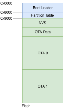
OTA Flash Partitions
The typical state changes that happen across the OTA firmware upgrade workflow are as shown in the figure.
Step 0: OTA 0 is the active firmware. The OTA data partition stores this information as can be seen.
Step 1: The firmware upgrade process begins. The passive partition is identified, erased and new firmware is being written to the OTA 1 partition.
Step 2: The firmware upgrade is completely written and verification is in-progress.
Step 3: The firmware upgrade is successful, the OTA data partition is updated to indicate that OTA 1 is now the active partition. On the next boot-up the firmware from this partition will boot.
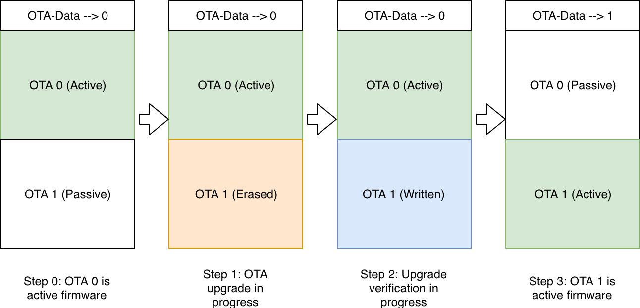
Firmware Upgrade Flow
Updating the Flash Partitions
So how exactly do we instruct the IDF to create a partition table that has this OTA-Data partition and the 2 partitions for storing the firmware?
This can be achieved by creating a partitions file. This is a simple CSV (Comma Separated Values) file that instructs IDF what are the partitions that we want, what should be their size and how should they be placed.
The partitions file that is used for this example is shown below:
# Name,   Type, SubType, Offset,  Size, Flags
# Note: if you change the phy_init or app partition offset
# make sure to change the offset in Kconfig.projbuild
nvs,      data, nvs,     ,        0x6000,
otadata,  data, ota,     ,        0x2000,
phy_init, data, phy,     ,        0x1000,
ota_0,    app,  ota_0,   ,        1600K,
ota_1,    app,  ota_1,   ,        1600K,
The above partitions file instructs the IDF to create partitions: NVS, OTA-Data, OTA 0 and OTA 1, and it also specifies the sizes for each of these.
Once we create this partition file, we should instruct IDF to use this custom partitioning mechanism, over its default mechanism. This can be enabled by updating the SDK configuration. In the case of our application right now, this setting has already been activated in the 6_ota/sdkconfig.defaults file. Hence you don’t have to do any extra step for activating this.
But should you wish to use a different partitions file, or update the offset of the primary firmware, you should modify this setting. This can be done by executing the idf.py menuconfig command, and then configuring correct options in menuconfig -> Partition Table.
The Code
Now let’s check the code for actually performing the firmware upgrade.
esp_http_client_config_t config = {
    .url = url,
    .crt_bundle_attach = esp_crt_bundle_attach,
};
esp_err_t ret = esp_https_ota(&config);
The esp_http_client_config_t structure is used to define the OTA upgrade source. This includes the URL that should be upgraded from. For server certificate validation, this implementation uses ESP-IDF’s built-in certificate bundle (esp_crt_bundle_attach) instead of embedding individual CA certificates. This provides automatic validation for most common certificate authorities.
The API esp_https_ota() is then executed which initiates the firmware upgrade. When the firmware upgrade process is successful (or fails), this API returns with the appropriate error code.
By default, the certificate bundle includes certificates for most common certificate authorities, including GitHub. This makes it easy for you to host your upgrade image on GitHub and try out the upgrades.
Send Firmware Upgrade URL
The open question is how does the device receive the upgrade URL. The firmware upgrade command is typically different from the remote-control commands discussed in the earlier section. This is because the firmware upgrade is generally triggered by the device manufacturer for a batch or group of devices based on certain criteria.
For the sake of simplicity, we will use the same remote control infrastructure to pass the firmware upgrade URL command to the device. But note that in your production scenario, you will send this firmware upgrade URL using some other mechanism controlled through the cloud.
For quickly trying out firmware upgrades, we have sample firmware images (of the 1_hello_world application) uploaded on GitHub for all supported platforms. We can try to upgrade to these firmware images as follows:
curl -d '{"state":{"desired":{"ota_url":"https://raw.githubusercontent.com/wiki/espressif/esp-jumpstart/images/esp32/1_hello_world.bin"}}}' \
        --tlsv1.2 --cert cloud_cfg/device.cert \
        --key cloud_cfg/device.key \
        https://a3orti3lw2padm-ats.iot.us-east-1.amazonaws.com:8443/things/<contents-of-deviceid.txt-file>/shadow | python -mjson.tool
Note: For other platforms, use the following URLs: - ESP32-C3: https://raw.githubusercontent.com/wiki/espressif/esp-jumpstart/images/esp32c3/1_hello_world.bin - ESP32-C6: https://raw.githubusercontent.com/wiki/espressif/esp-jumpstart/images/esp32c6/1_hello_world.bin - ESP32-S2: https://raw.githubusercontent.com/wiki/espressif/esp-jumpstart/images/esp32s2/1_hello_world.bin - ESP32-S3: https://raw.githubusercontent.com/wiki/espressif/esp-jumpstart/images/esp32s3/1_hello_world.bin
After the firmware upgrade is successful, the device will now execute the Hello World firmware.
Progress So Far
With this firmware we enable a key feature of any smart connected device, the over-the-air firmware upgrade.
Our product firmware is almost ready to be go, but for the final considerations for maintaining unique device data. Let’s wrap that up in the upcoming Chapter.