ESP DevKit Board Short Circuit Analysis and Measurement
Note
This document is automatically translated using AI. Please excuse any detailed errors. The official English version is still in progress.
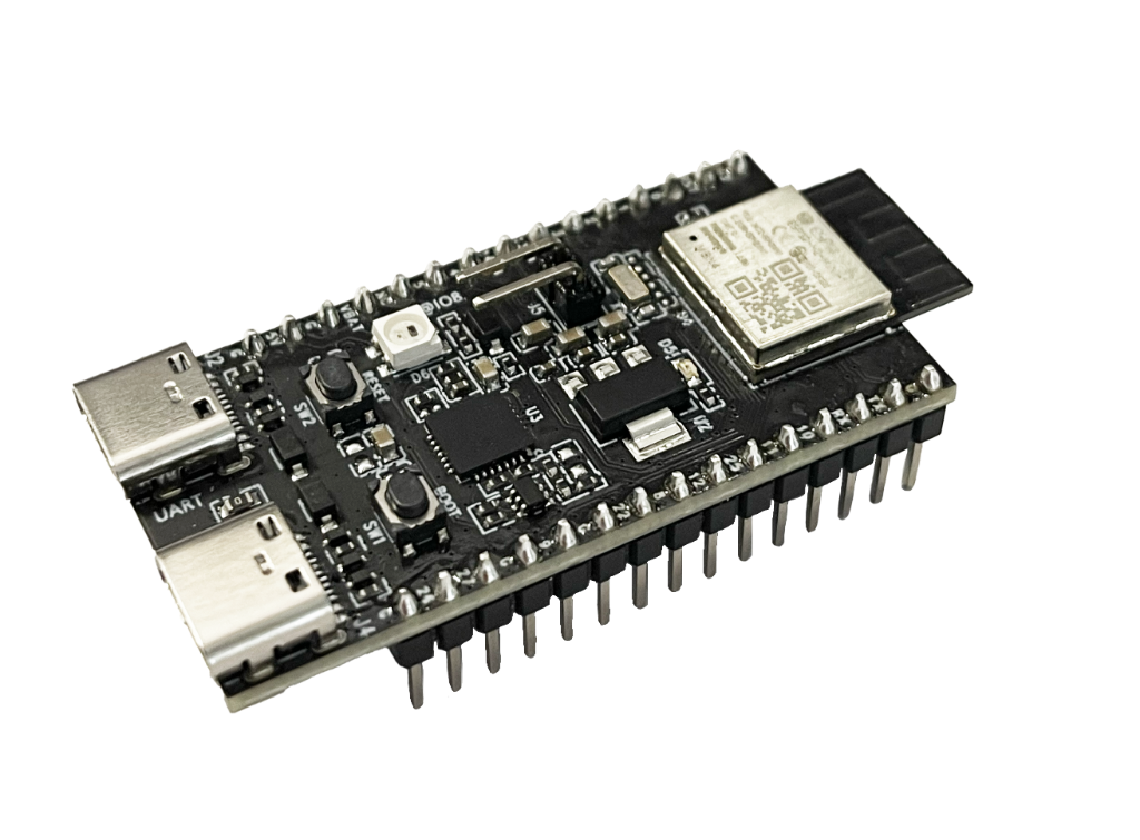
If the development board or module heats up after power-on and the indicator light does not turn on, it is highly suspected to be a power short circuit or overload. The following are systematic troubleshooting methods (using ESP32-H2-DevKitM-1-N4 as an example):
Step 1: Immediate Power-off Protection
Do not repeatedly power on the board. Overheating indicates a large current flowing through, and repeated power-ons may burn the chip or PCB copper foil.
Step 2: Visual Inspection
After powering off, inspect with the naked eye or a magnifying glass:
Are there any solder bridges (shorted pins) between solder joints?
Are there any burn marks or abnormal odors on the board?
Are components like capacitors or LDOs burst or discolored?
Are there any foreign objects shorting inside the USB port?
Step 3: Measure Static Resistance with a Multimeter
With the board completely powered off, use a multimeter in resistance mode (or continuity mode) to measure:
Measurement Point |
Normal Reference Value |
Abnormal Condition |
|---|---|---|
3V3 Pin → GND |
Usually > 1000Ω (cold state) |
< 100Ω generally confirms a short circuit |
5V (VBUS) → GND |
Usually > 1000Ω |
Close to 0Ω indicates a short on the USB power side |
Each GPIO → GND |
High impedance |
Close to 0Ω indicates the pin is shorted to ground |
Note
When measuring, connect the red probe to the node being measured and the black probe to GND. Capacitor charging and discharging will cause the resistance to start low and then rise; wait until it stabilizes before reading.
Step 4: Locate the Short Circuit
If a short circuit from 3V3 or VBUS to GND is confirmed, narrow down the scope further:
Method A: Partition Disconnection
Unplug all externally connected modules, jumpers, and connectors on the board, leaving only the core board.
Measure 3V3 → GND again. If it returns to normal → the issue is with the external parts.
If it is still shorted → the issue is on the core board itself.
Method B: Current-limited Power-on (Thermal Imaging / Tactile Location)
Use an adjustable current-limiting power supply (e.g., set to 3.3V / current limit 100mA) to power the board.
Use a thermal imager or cautiously quickly sweep your fingers across the board. The hottest component is the short circuit point.
Common heating points: LDO regulators (U1/U2 area), decoupling capacitors (broken down).
Method C: Voltage Drop Tracking
After applying current-limited power, use the DC voltage mode of a multimeter to measure point by point along the power path.
The short circuit is located between the two points where the voltage drops sharply.
Step 5: Summary of Common Short Circuit Causes
Cause |
Inspection Method |
|---|---|
SMD capacitor (bypass capacitor) broken down |
Remove suspected capacitors one by one and re-measure resistance |
LDO internal breakdown |
Remove LDO and re-measure input/output terminals |
Solder bridges |
Inspect all solder joints with a magnifying glass |
USB port pins shorted by solder |
Focus on VBUS/GND pins |
ESD damaged GPIO internals |
GPIO to GND resistance is abnormally low |
Recommended Tool List
Multimeter (essential)
Adjustable current-limiting power supply (highly recommended to protect the board)
Thermal imager / temperature gun (to locate heating points)
Magnifying glass / microscope (to check for solder bridges)
Hot air gun (to remove suspected broken-down capacitors)
Note
Most likely scenarios: A decoupling capacitor broken down by static electricity, or a damaged LDO. Both can be easily located using thermal imaging or touch after powering on with a current-limiting power supply.