ESP32-S2-HMI-DevKit-1 V1.0
This user guide will help you get started with ESP32-S2-HMI-DevKit-1 and will also provide more in-depth information.
ESP32-S2-HMI-DevKit-1 has been specifically designed for human-machine interfaces in smart-home automation controllers, smart speakers with display, smart alarm clocks, etc. This development kit supports rapid secondary development, since developers can take advantage of the kit’s various onboard resources and expansion interfaces, in order to develop various functions.
The main features of the board are listed below:
Module Embedded: ESP32-S2-WROVER module with 4 MB flash and 2 MB PSRAM
Display: 4.3-inch TFT-LCD which uses 16-bit 8080 parallel port with 480×800 resolution and 256-level hardware DC backlight adjustment circuit, connected to an I2C capacitive touch panel
Audio: Audio amplifier, built-in microphone, speaker connector
Storage: microSD card connector
Sensors: 3-axis accelerometer, 3-axis gyroscope, ambient light sensor, temperature and humidity sensors
Expansion: SPI header, TWAI interface (compatible with CAN 2.0), I2C ADC, UART/Prog header
LEDs: Programmable RGB LED and IR LED
Buttons: Wake Up and Reset buttons
USB: 1 x USB-C OTG (DFU/CDC) port, 1 x USB-C debug port
Power Supply: 5V and 3.3V power headers
Optional Rechargeable Battery: 1,950 mAh single-core lithium battery with a charge IC
ESP32-S2-HMI-DevKit-1 with ESP32-S2-WROVER module
The document consists of the following major sections:
Getting started: Overview of the board and hardware/software setup instructions to get started.
Hardware Reference: More detailed information about the board’s hardware.
Related Documents: Links to related documentation.
Getting Started
This section provides a brief introduction of ESP32-S2-HMI-DevKit-1, instructions on how to do the initial hardware setup and how to flash firmware onto it.
Description of Components
ESP32-S2-HMI-DevKit-1 is an HMI development board designed based on the ESP32-S2. The following figure describes its key on-board resources:
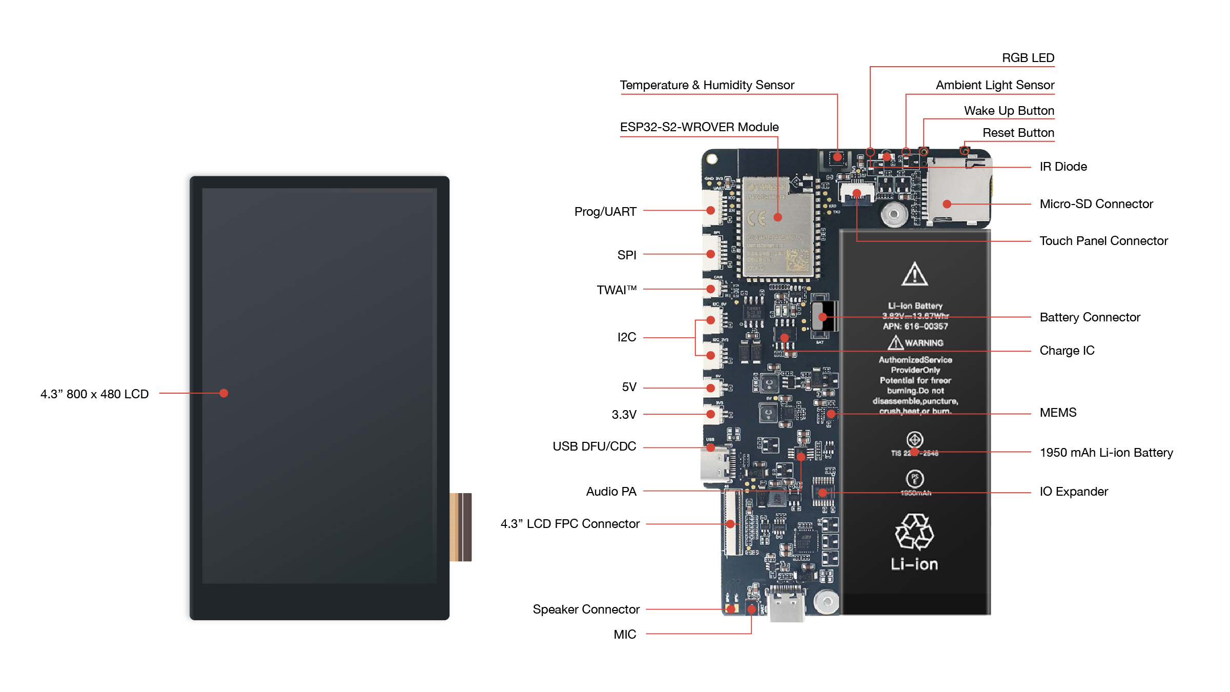
ESP32-S2-HMI-DevKit-1 (click to enlarge)
The key components of the board are described in a clockwise direction.
Key Component |
Description |
|---|---|
ESP32-S2-WROVER Module |
ESP32-S2-WROVER is a powerful, generic Wi-Fi MCU module that integrates ESP32-S2. It has a PCB antenna, a 4 MB external SPI flash and an additional 2 MB PSRAM. |
Temperature & Humidity Sensor |
Temperature & humidity sensors for detecting ambient temperature and humidity. Read via the I2C bus. |
RGB LED |
Addressable RGB LED (WS2812), driven by GPIO21. Can switch between the LED and IR LED via IO expander. |
Ambient Light Sensor |
Ambient Light Sensor used to detect ambient light intensity. Read via the I2C bus. |
Wake Up Button |
Download button. Press and hold the Boot button while pressing the Reset button to initiate the “firmware download” mode to download the firmware via the serial port. This button can also be configured to wake up the device from deep sleep mode. |
Reset Button |
Press this button to restart the system. |
IR LED |
Infrared emitting diode, driven by GPIO21. Can switch between RGB LED and IR LED via IO expander. |
Charge IC |
Charge battery. |
MEMS |
3-axis accelerometer and 3-axis gyroscope. |
1950 mAh Li-ion Battery |
An optional 1,950 mAh rechargeable lithium battery. |
IO Expander |
Expand GPIO through I2C bus. |
MIC |
On-board simulated microphone. |
Audio PA |
Audio amplifier. |
4.3” 800 × 480 LCD |
A 4.3-inch TFT-LCD which uses 16-bit 8080 parallel port with 480×800 resolution, and 256-level hardware DC backlight adjustment circuit. It is connected with an I2C capacitive touch panel overlay. |
Start Application Development
Before powering up your board, please make sure that it is in good condition with no obvious signs of damage.
Required Hardware
1 x PC loaded with Windows, macOS or Linux (Linux operating system is recommended)
1 x ESP32-S2-HMI-DevKit-1
1 x USB-C cable (it is recommended to prepare two USB-C cables if you want to evaluate MCU’s USB functions)
1 x Speaker (8 Ohm, 2 W)
1 x microSD card (some examples may have large storage needs)
Note
Be sure to use an appropriate USB cable. Some cables are for charging only and do not provide the needed data lines nor work for programming the boards.
Hardware Setup
To facilitate your quick evaluation of all examples, please follow these steps to set up the board:
Insert microSD card into the connector. Please make sure all the important data is backed up, as the microSD card may be formatted if its partition format is not FAT.
If you need to evaluate the audio playback function, please connect the speaker pad near the USB port on the bottom of the board to the supplied speaker, or to another speaker with a similar size (8 Ohm, 2 W).
Software Setup
First, please make sure you have configured the ESP-IDF development environment correctly. To ensure this, please enter idf.py --version in your terminal and if the output is similar to ESP-IDF v4.2-dev-2084-g98d5b5dfd, it means you have installed ESP-IDF correctly. For detailed information about installation and configuration, please refer to ESP-IDF Get Started.
After configuration completed, you can switch back to the esp-dev-kits/esp32-s2-hmi-devkit-1 directory. All code examples are placed under the examples directory, you can build projects by running idf.py build.
Project Options
Various examples are provided for ESP32-S2-HMI-DevKit-1 as shown below:
Printing “Hello world!” on screen: examples/esp32-s2-hmi-devkit-1/examples/get-started/hello_world
Blinking WS2812 LED and showing the color on screen: examples/esp32-s2-hmi-devkit-1/examples/get-started/led_blink
Starting a UI to configure Wi-Fi credential: examples/esp32-s2-hmi-devkit-1/examples/get-started/provision
Acquiring audio with ADC from the output of analog MIC: examples/esp32-s2-hmi-devkit-1/examples/audio/audio_record
Playing music: examples/esp32-s2-hmi-devkit-1/examples/audio/music_player
Shutting down selected board area into a deep sleep: examples/esp32-s2-hmi-devkit-1/examples/power
Using Freetype to render fonts: examples/esp32-s2-hmi-devkit-1/examples/freetype
Using on-board sensors: examples/esp32-s2-hmi-devkit-1/examples/sensors
Using smart panel: examples/esp32-s2-hmi-devkit-1/examples/smart-panel
Viewing files on SD card: examples/esp32-s2-hmi-devkit-1/examples/storage/sdcard_fatfs
USB flash disk: examples/esp32-s2-hmi-devkit-1/examples/storage/usb_msc
You can configure project options by entering idf.py menuconfig in each example directory.
Please make sure to correctly configure the following options in menuconfig:
(Top) > HMI Board Config > HMI board: Select board version. By default, please selectESP32-S2-HMI-DevKit-V2;(Top) > HMI Board Config > Audio HAL: Select audio output interface, whether to use PWM or DAC;(Top) > HMI Board Config > LCD Drivers: Select display IC type for LCD. By default, ESP32-S2-HMI-DevKit-1 uses RM68120 as its display IC;In
(Top) > Component config > ESP32S2-specific, please go to theSupport for external, SPI-connected RAMoption:Go to
SPI RAM config > Set RAM clock speed, and set the PSRAM clock as80 MHz clock speed;
(Top) -> Component config -> FreeRTOS: setTick rate (Hz)as 1000.
In each example folder, we have provided a default configuration file named sdkconfig.defaults, with above options configured correctly.
ESP-IDF Version Dependencies
The examples/esp32-s2-hmi-devkit-1/examples/storage/usb_msc example needs to be built in IDF v4.3, while other examples can be built in IDF v4.2 and later versions.
Notice: Due to strict regulation on battery export, for deliveries outside of China mainland, we are shipping ESP32-S2-HMI-DevKit-1 without the battery. As a substitute, you can use the iPhone 5 replacement battery (the connector type is non-standard). The battery capacity is not critical.
Contents and Packaging
Retail Orders
If you order one or several samples of the kit, each ESP32-S2-HMI-DevKit-1 development kit comes in an individual package.

ESP32-S2-HMI-DevKit-1 package
The contents are as follows:
Development board - ESP32-S2-HMI-Devit-1
Cables - SH1.25 to 2.54mm cables x 7
For retail orders, please go to https://www.espressif.com/en/company/contact/buy-a-sample.
Wholesale Orders
If you order in bulk, the boards come in large cardboard boxes.
For wholesale orders, please go to https://www.espressif.com/en/contact-us/sales-questions.
Hardware Reference
Block Diagram
The block diagram below shows the components of ESP32-S2-HMI-DevKit-1 and their interconnections.

ESP32-S2-HMI-DevKit-1 block diagram
Power Supply Options
The power of the ESP32-S2-HMI-DevKit-1 development board is divided into a 5 V power domain and a 3.3 V power domain, so as to reduce power consumption, improve power efficiency and support battery charging, part of which can be controlled by software whereas the other part is fixed in the hardware design.
To reduce current consumption, the preloaded firmware will power off all controlled power domains and put all ICs in low-power mode.
For more information, please refer to Power.
Connectors
It provides multiple extended interfaces for customized development. The connectors of the board are described in a clockwise direction. Please refer to ESP32-S2-HMI-DevKit-1 key on-board resources.
Connectors |
Description |
|---|---|
Speaker Connector |
To connect a speaker. |
4.3” LCD FPC Connector |
(Reserved) Connect to the supported 4.3” LCD extension board using the FPC cable. |
USB DFU/CDC |
1 x USB-C OTG (DFU/CDC) port, 1 x USB-C debug port. |
3.3 V Connector |
3.3 V power header. |
5 V Connector |
5 V power header. |
I2C Connector |
I2C connector with 5 V/3.3 V power supply options. |
TWAI interface (compatible with CAN 2.0) |
Two-wire automotive interface. |
SPI |
Can connect devices on the SPI bus if the SD card is not in use. |
Prog/UART |
This interface is used to observe log output and firmware flash. |
microSD Connector |
Insert microSD card to expand the storage space of the device. |
Battery Connector |
To connect a battery. |
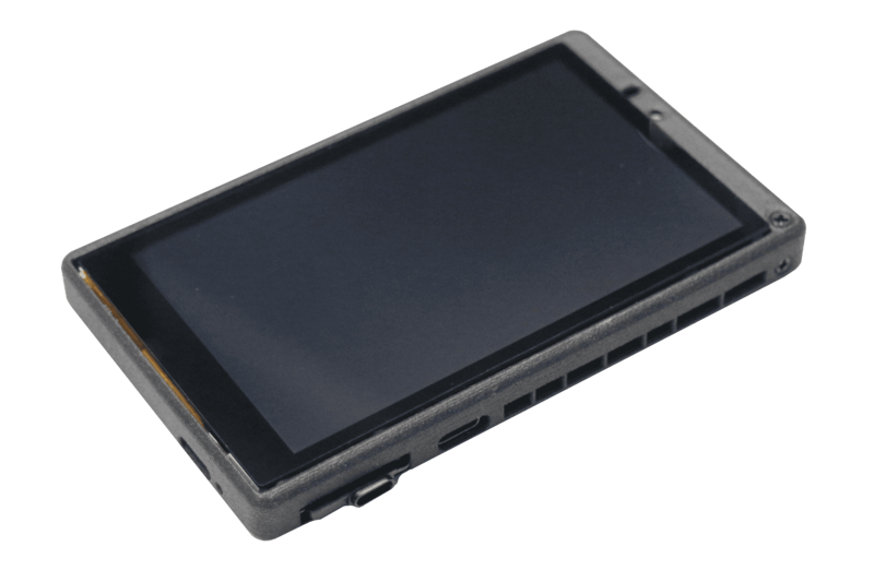
Below is the back view of the board for your reference.

ESP32-S2-HMI-DevKit-1 - back view