Power
The power of the ESP32-S2-HMI-DevKit-1 development board is divided into a 5 V power domain and a 3.3 V power domain, so as to reduce power consumption, improve power efficiency and support battery charging. Part of the power domain can be controlled by software whereas the other part is configured as permanently enabled in hardware design.
To reduce current consumption, the preloaded firmware will power off all controlled power domains and put all ICs to low-power mode.
3.3 V Power Domain
Most of the ICs and modules are powered by the 3.3 V power domain, which can be divided into an uncontrolled 3.3 V power domain and a controlled 3.3 V power domain.
The uncontrolled 3.3 V power domain cannot be powered off via software, and provides power for the Buck circuit. When there is a power supply from USB, this power domain will obtain power from the 5 V input through the USB cable; when USB is disconnected, it will obtain 3.6 ~ 4.2 V power from the lithium battery. This power domain mainly provides power for the ESP32-S2-WROVER module and other devices which can enter low-power mode via software control.
The controlled 3.3 V power domain comes from the uncontrolled 3.3 V power domain and is turned on/off via a PMOS control switch, which is connected to the P4 pin of the IO expander. This power domain mainly provides power for ICs with higher static power consumption and cannot enter low-power mode.
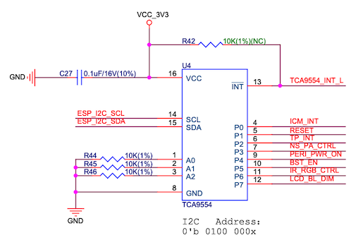
ESP32-S2-HMI-DevKit-1 IO expander schematic
5 V Power Domain
The 5 V power domain of the development board provides power for the audio amplifier and the TWAI® transceiver. It obtains power from the following resources:
The USB port
The power input from external 5 V power port
The power passing through the Booster circuit from the lithium battery
The power obtained from USB and the external 5 V power input supplies power for all devices (except CP2102N) that require 5 V power and cannot be disconnected by software. When obtaining power from the lithium battery, the EN pin level of the Booster IC can be controlled via the P5 pin of the IO expander to enable 5 V power in high level.
The power input through the USB port on the bottom of the board is split into two lines: one provides power for CP2102N while the other becomes USB_5V after passing through a diode. The CP2102N will only be powered up when this USB port is connected, since it only needs to be in operation when the PC is connected. Any 5 V power input will cause the Booster IC to be powered off and charge the on-board lithium battery via the charging IC.
Power Dependencies
The following functions depend on the 5 V power domain:
TWAI® (selects available power supply from USB 5 V or Booster 5 V automatically)
Audio amplifier (gets power supply from USB 5 V, if it fails, will try from the battery)
5 V power output connector (the same as TWAI®)
The following functions depend on the controlled 3.3 V power domain:
Micro-SD card
Microphone and its bias circuit, and operational amplifier
Display and touch function
WS2812 RGB LED and IR LED
IR LED
Power State
When the development board is connected via the USB cable, the 5 V power domain is powered on automatically and the charging IC outputs voltage to supply power for the battery. In this case, the controlled 3.3 V power domain is controlled by the P4 pin of the IO expander.
When the development board is powered by the battery, the controlled 3.3 V power domain is controlled by the P4 pin of the IO expander while the 5 V power domain is controlled by the P5 pin of the IO expander, and the charging IC will not work.