ESP Sensorless BLDC Control Components
本指南包含以下内容:
目录
esp_sensorless_bldc_control 组件是基于 ESP32 系列芯片的 BLDC 无感方波控制库。目前以及支持以下功能:
基于ADC 采样检测过零点
基于支持比较器检测过零点
基于脉冲法实现转子初始相位检测
堵转保护
本文主要讲解如何使用 esp_sensorless_bldc_control 组件进行无刷电机开发,不涉及原理讲解,如需了解更多原理请参考
无刷电机控制概述 无刷电机控制概述
基于 ADC 采样的无感方波电机控制 ADC 采样检测过零点
基于比较器检测的无感方波电机控制 比较器检测过零点
无感方波控制流程主要可以分为以下部分
INJECT:注入阶段,通过脉振高频电压注入得到初始相位
INJECTALIGNMENT:对齐阶段,将转子固定到初始相位
ALIGNMENTDRAG:强托阶段,通过六步换向将转子转动起来
DRAGCLOSED_LOOP:无感闭环控制,通过检测反电动势过零点进行换向
CLOSED_LOOPBLOCKED:电机堵转
BLOCKEDSTOP: 电机停止
STOPFAULT: 电机故障
FAULT
接下来会分别介绍各个部分的具体流程以及需要注意的参数
INJECT
通过脉振注入法获取电机初始相位,需要在逆变电路的低端采集母线电流。如下图所示:
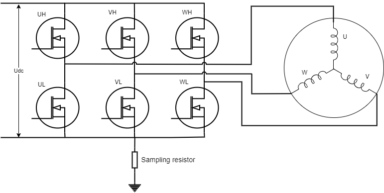
BLDC 母线电流采集
备注
由于电流不能直接被采集到,因此通过一个采样电阻,可以将电流转化为电压。注意,电压需要转化到 ESP32 ADC 能够采集的范围。请参考:ESP32 ADC
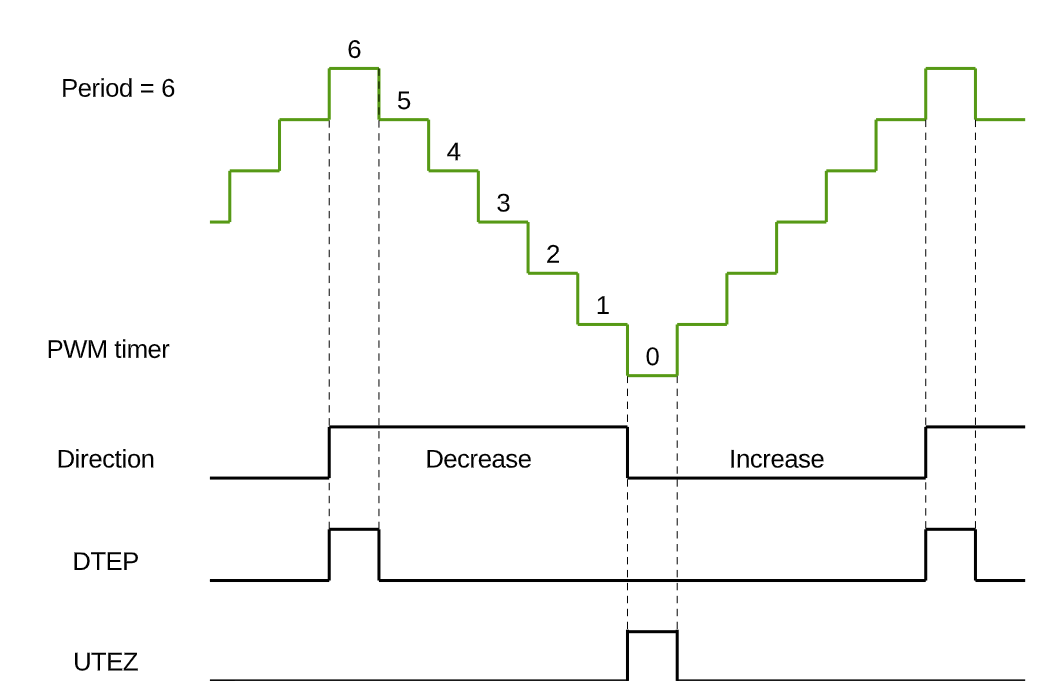
由于电流只存在于上下管均导通的情况,因此需要在上管导通的时候进行 ADC 采样。将 MCPWM 配置为上升下降模式,并在计数器达到顶峰的时候进行采样,可以采集到准确的母线电压。
MCPWM 上升下降模式
备注
LEDC 驱动不支持在高电平时候触发回调,因此使用 LEDC 方式驱动的方案`无法使用` INJECT 模式。
INJECT_ENABLE 为 1 时,开启 INJECT 模式,否则关闭。默认为 0。PWM 的生成模式必须为 MCPWM
INJECT_DUTY 注入的电压大小,一般都是采用高占空比注入
CHARGE_TIME 电感充电时间和脉冲注入时间,该值影响到初始相位检测的精准性。这个值太小会导致采集到的 ADC 值为 0,太大会导致 ADC 值过大。以手动旋转电机,在一圈中可以获得稳定的相位 1-6,不出现错误相位 0 和 7 为佳。
ALIGNMENT
为保障无刷电机能够正常启动,需要确定转子在静止时的位置。在实际的应用中,通过在任意一组绕组上通电一定时间,将转子固定到固定相位,为后面的强拖做准备。
ALIGNMENTNMS 对齐时间,时间太长会过流。时间太短可能会导致转子没有对齐到正确的相位。
ALIGNMENTDUTY 对齐的力度。
DRAG
通过六步换向将转子拖动起来,转子拖动采用升压升频的方式。逐渐的加大电压和换向频率,使电机具有初始速度,有明显的反电动势。以电机拖动过程中无异响,丝滑,无卡顿为佳。拖动时间无需太长。
RAMP_TIM_STA 拖动的初始延迟时间
RAMP_TIM_END 拖动的最小延迟时间
RAMP_TIM_STEP 拖动时间的步进
RAMP_DUTY_STA 拖动的初始占空比
RAMP_DUTY_END 拖动的最大占空比
RAMP_DUTY_INC 拖动占空比的步进
备注
强拖需要在电机工作环境下进行调参,电机空载参数不一定适用于带载情况
CLOSED_LOOP
ADC 采样检测过零点
ADC 采样检测过零点需要采集悬空相电压和电机电源电压,且需要在上管导通的时候进行采集。
备注
采用 ADC 检测过零点,必须使用 MCPWM 作为驱动
ENTER_CLOSE_TIME 设置进入闭环的时间,默认强拖一段时间后即可进行闭环控制。
ZERO_REPEAT_TIME 连续 N 次检测到过零点才认为是过零点。
AVOID_CONTINUE_CURRENT_TIME 在换向后,会存在续电流影响,通过延迟检测规避掉续电流
比较器检测过零点
比较器检测过零点是通过硬件比较器比较悬空相反电动势和母线电压,通过 GPIO 检测比较器信号翻转来判断过零点。由于在实际过程中会有很多噪点,需要多次检测来确认过零点。
ZERO_STABLE_FLAG_CNT 多次检测到稳定过零点信号后,进入无感控制
ZERO_CROSS_DETECTION_ACCURACY 连续 N 次检测到相同信号视为稳定信号 0xFF 为 8次,0XFFFF 为 16 次。当前支持的最大滤波次数为 0xFFFFFFFF,若依旧无法进入闭环状态,需要排查硬件问题。
备注
硬件排查方向主要包括采集三相端电压与比较器输出的滤波电容是否设置合理。
提前换向
过零点信号一般在换向前 30° 到来,当检测到过零点信号后,只需要延迟 30° 的时间即可。但在电机旋转过程中,电气周期不固定以及存在软件滤波和时延等原因,需要稍微补偿一下换向时间。
ZERO_CROSS_ADVANCE 提前换向时间,提前角度为 180 / ZERO_CROSS_ADVANCE, 默认为 6
备注
换向角度并不是越提前约好,可以搭配示波器观测计算的换向角度与实际的换向角度是否一致。
堵转保护
电机长时间不换相即可视为堵转,此时会停止电机运行,进入堵转保护状态。
速度控制
通过 PID 控制速度,使电机达到设定的速度。
SPEED_KP 速度控制的 P 值
SPEED_KI 速度控制的 I 值
SPEED_KD 速度控制的 D 值
SPEED_MIN_INTEGRAL 速度控制的积分最小值
SPEED_MAX_INTEGRAL 速度控制的积分最大值
SPEED_MIN_OUTPUT 速度控制的输出最小值
SPEED_MAX_OUTPUT 速度控制的输出最大值,不超过最大占空比
SPEED_CAL_TYPE 位置式 PID 还是增量式 PID
SPEED_MAX_RPM 最大转速 RPM
SPEED_MIN_RPM 最小转速 RPM
MAX_SPEED_MEASUREMENT_FACTOR 为了避免错误的速度检测,如果检测到的速度大于此设定系数,则视为错误速度检测。
API 参考
Header File
Functions
-
ESP_EVENT_DECLARE_BASE(BLDC_CONTROL_EVENT)
using esp_event_handler_register() to register BLDC_CONTROL_EVENT
esp event name
-
esp_err_t bldc_control_init(bldc_control_handle_t *handle, bldc_control_config_t *config)
init bldc control
- 参数
handle – pointer to bldc control handle
config – pointer to bldc control config
- 返回
ESP_ERR_INVALID_ARG if handle or config is NULL ESP_ERR_NO_MEM if memory allocation failed ESP_OK on success ESP_FAIL on other errors
-
esp_err_t bldc_control_deinit(bldc_control_handle_t *handle)
deinit bldc control
- 参数
handle – pointer to bldc control handle ESP_ERR_INVALID_ARG if handle or config is NULL ESP_OK on success ESP_FAIL on other errors
-
esp_err_t bldc_control_start(bldc_control_handle_t *handle, uint32_t expect_speed_rpm)
motor start
- 参数
handle – pointer to bldc control handle
expect_speed_rpm – expect speed in rpm. This parameter does not work in case of open-loop control
- 返回
ESP_OK on success
-
esp_err_t bldc_control_stop(bldc_control_handle_t *handle)
motor stop
- 参数
handle – pointer to bldc control handle
- 返回
ESP_FAIL if motor stop failed ESP_OK on success
-
dir_enum_t bldc_control_get_dir(bldc_control_handle_t *handle)
get current motor direction
- 参数
handle – pointer to bldc control handle
- 返回
dir_enum_t current motor direction
-
esp_err_t bldc_control_set_dir(bldc_control_handle_t *handle, dir_enum_t dir)
set motor direction
- 参数
handle – pointer to bldc control handle
dir – motor direction
- 返回
ESP_OK on success
-
int bldc_control_get_duty(bldc_control_handle_t *handle)
get current motor pwm duty
- 参数
handle – pointer to bldc control handle
- 返回
int current motor pwm duty
-
esp_err_t bldc_control_set_duty(bldc_control_handle_t *handle, uint16_t duty)
set motor pwm duty, Closed-loop speed control without calls
- 参数
handle – pointer to bldc control handle
duty – motor pwm duty
- 返回
ESP_OK on success
-
int bldc_control_get_speed_rpm(bldc_control_handle_t *handle)
get current RPM
- 参数
handle – pointer to bldc control handle
- 返回
int current RPM
-
esp_err_t bldc_control_set_speed_rpm(bldc_control_handle_t *handle, int speed_rpm)
set motor RPM
- 参数
handle – pointer to bldc control handle
speed_rpm – motor RPM
- 返回
ESP_OK on success
Structures
-
struct bldc_debug_config_t
Debug configuration, when activated, will periodically invoke the debug_operation.
-
struct bldc_control_config_t
BLDC Control Configuration.
Public Members
-
speed_mode_t speed_mode
Speed Mode
-
control_mode_t control_mode
Control Mode
-
alignment_mode_t alignment_mode
Alignment Mode
-
bldc_six_step_config_t six_step_config
six-step phase change config
-
bldc_zero_cross_comparer_config_t zero_cross_comparer_config
Comparator detects zero crossing config
-
bldc_debug_config_t debug_config
debug config
-
speed_mode_t speed_mode
Type Definitions
-
typedef void *bldc_control_handle_t
bldc control handle
Enumerations
-
enum bldc_control_event_t
Values:
-
enumerator BLDC_CONTROL_START
BLDC control start event
-
enumerator BLDC_CONTROL_ALIGNMENT
BLDC control alignment event
-
enumerator BLDC_CONTROL_DRAG
BLDC control drag event
-
enumerator BLDC_CONTROL_STOP
BLDC control stop event
-
enumerator BLDC_CONTROL_CLOSED_LOOP
BLDC control closed loop event
-
enumerator BLDC_CONTROL_BLOCKED
BLDC control blocked event
-
enumerator BLDC_CONTROL_START
Header File
Macros
-
BLDC_LEDC
-
BLDC_MCPWM
-
PWM_MODE
Configure the generation of PWM.
Configure the generation of PWM.
-
MCPWM_CLK_SRC
MCPWM Settings.
Number of count ticks within a period time_us = 1,000,000 / MCPWM_CLK_SRC
-
MCPWM_PERIOD
pwm_cycle_us = 1,000,000 / MCPWM_CLK_SRC * MCPWM_PERIOD
-
FREQ_HZ
LEDC Settings.
-
DUTY_RES
Set duty resolution to 11 bits
-
ALARM_COUNT_US
No changes should be made here.
-
DUTY_MAX
-
PWM_DUTYCYCLE_05
-
PWM_DUTYCYCLE_10
-
PWM_DUTYCYCLE_15
-
PWM_DUTYCYCLE_20
-
PWM_DUTYCYCLE_25
-
PWM_DUTYCYCLE_30
-
PWM_DUTYCYCLE_40
-
PWM_DUTYCYCLE_50
-
PWM_DUTYCYCLE_60
-
PWM_DUTYCYCLE_80
-
PWM_DUTYCYCLE_90
-
PWM_DUTYCYCLE_100
-
INJECT_ENABLE
Pulse injection-related parameters.
备注
Used to detect the initial phase of the motor; MCPWM peripheral support is necessary. Whether to enable pulse injection.
-
INJECT_DUTY
Injected torque.
-
CHARGE_TIME
Capacitor charging and injection time.
-
ALIGNMENTNMS
Parameters related to motor alignment. Used to lock the motor in a specific phase before strong dragging.
Duration of alignment, too short may not reach the position, too long may cause the motor to overheat.
-
ALIGNMENTDUTY
alignment torque.
-
RAMP_TIM_STA
Setting parameters for strong dragging. The principle of strong dragging is to increase the control frequency and intensity.
备注
If the control cycle speeds up, corresponding reductions should be made to the RAMP_TIM_STA, RAMP_TIM_END, RAMP_TIM_STEP The start step time for climbing. A smaller value results in faster startup but may lead to overcurrent issues.
-
RAMP_TIM_END
The end step time for climbing, adjusted based on the load. If loaded, this value should be relatively larger.
-
RAMP_TIM_STEP
Decremental increment for climbing step time—adjusted in accordance with RAMP_TIM_STA.
-
RAMP_DUTY_STA
The starting torque for climbing.
-
RAMP_DUTY_END
The ending torque for climbing.
-
RAMP_DUTY_INC
The incremental torque step for climbing—too small a value may result in failure to start, while too large a value may lead to overcurrent issues.
-
ENTER_CLOSE_TIME
ADC parameters for zero-crossing detection; please do not delete if not in use.
Enter the closed-loop state delay times.
-
ZERO_REPEAT_TIME
Change phase after detecting zero-crossing signals continuously for several times.
-
AVOID_CONTINUE_CURRENT_TIME
Avoiding Continuous Current
-
ZERO_STABLE_FLAG_CNT
Comparator parameters for zero-crossing detection; please do not delete if not in use.
After stable detection for multiple revolutions, it is considered to enter a sensorless state.
-
ZERO_CROSS_DETECTION_ACCURACY
Count a valid comparator value every consecutive detection for how many times.
-
ZERO_CROSS_ADVANCE
Common parameter for compensated commutation time calculation.
Advance switching at zero-crossing, switching angle = 180°/ZERO_CROSS_ADVANCE. angle compensation should be provided. >= 6
-
POLE_PAIR
Motor parameter settings.
Number of pole pairs in the motor.
-
BASE_VOLTAGE
Rated voltage.
-
BASE_SPEED
Rated speed unit: rpm.
-
SPEED_KP
Closed-loop PID parameters for speed.
P
-
SPEED_KI
I
-
SPEED_KD
D
-
SPEED_MIN_INTEGRAL
Minimum integral saturation limit.
-
SPEED_MAX_INTEGRAL
Maximum integral saturation limit.
-
SPEED_MIN_OUTPUT
Minimum PWM duty cycle output.
-
SPEED_MAX_OUTPUT
Maximum PWM duty cycle output.
-
SPEED_CAL_TYPE
0 Incremental 1 Positional
-
SPEED_MAX_RPM
Speed parameter settings.
Maximum speed.
-
SPEED_MIN_RPM
Minimum speed.
-
MAX_SPEED_MEASUREMENT_FACTOR
Supports a measured speed range from 0 to 1.2 times SpeedMAX. Large values could prevent proper filtering of incorrect data.