ESP Sensorless BLDC Control Components
This guide includes the following content:
Table of Contents
The esp_sensorless_bldc_control component is a sensorless BLDC square wave control library based on the ESP32 series chips. It currently supports the following features:
Zero-crossing detection based on ADC sampling
Zero-crossing detection supported by comparators
Rotor initial phase detection based on the pulse method
Stall protection
This article mainly explains how to use the esp_sensorless_bldc_control component for brushless motor development and does not cover the principles. For more information on the principles, please refer to:
Overview of Bldc Motor Control Overview of Brushless Motor Control
Sensorless Square Wave Motor Control Based on ADC Sampling Zero-crossing Detection Based on ADC Sampling
Sensorless Square Wave Motor Control Based on Comparator Detection Zero-crossing Detection Based on Comparators
The sensorless square wave control process can be mainly divided into the following parts:
INJECT: Injection phase, obtaining the initial phase through high-frequency voltage pulses
INJECTALIGNMENT: Alignment phase, fixing the rotor to the initial phase
ALIGNMENTDRAG: Drag phase, rotating the rotor through six-step commutation
DRAGCLOSED_LOOP: Sensorless closed-loop control, commuting by detecting back EMF zero-crossing points
CLOSED_LOOPBLOCKED: Motor stall
BLOCKEDSTOP: Motor stop
STOPFAULT: Motor fault
FAULT
Next, the specific processes of each part and the parameters to be noted will be introduced.
INJECT
The initial phase of the motor is obtained through pulse injection, and the bus current is collected at the low end of the inverter circuit. As shown in the figure below:
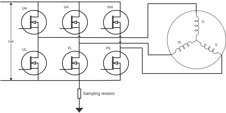
BLDC Bus Current Collection
Note
Since the current cannot be collected directly, a sampling resistor is used to convert the current into voltage. Note that the voltage needs to be converted to a range that the ESP32 ADC can collect. Please refer to: ESP32 ADC
Since the current only exists when both the upper and lower tubes are conducting, ADC sampling needs to be performed when the upper tube is conducting. Configure MCPWM in rising and falling mode and sample when the counter reaches the peak to accurately collect the bus voltage.
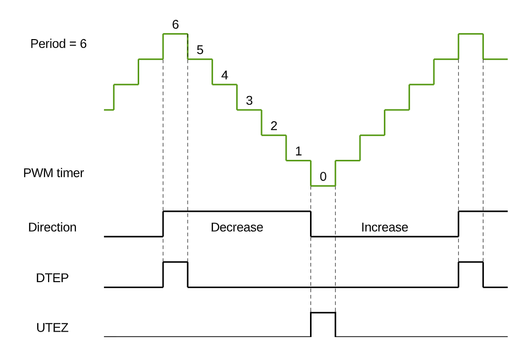
MCPWM Rising and Falling Mode
Note
The LEDC driver does not support callback triggering at high levels, so the INJECT mode cannot be used with the LEDC driving method.
INJECT_ENABLE is set to 1 to enable INJECT mode, otherwise, it is disabled. The default is 0. The PWM generation mode must be MCPWM.
INJECT_DUTY is the injected voltage size, generally using high duty cycle injection.
CHARGE_TIME is the inductance charging time and pulse injection time, which affects the accuracy of initial phase detection. If this value is too small, the collected ADC value will be 0; if it is too large, the ADC value will be too high. Manually rotate the motor, and it is best to obtain stable phases 1-6 in one turn without errors phases 0 and 7.
ALIGNMENT
To ensure the brushless motor can start normally, it is necessary to determine the position of the rotor when it is stationary. In practical applications, this is done by energizing a set of windings for a certain period, fixing the rotor in a specific phase, and preparing for subsequent forced commutation.
ALIGNMENTNMS Alignment time, if too long, it will overcurrent. If too short, the rotor may not be aligned to the correct phase.
ALIGNMENTDUTY Alignment force.
DRAG
The rotor is dragged through six-step commutation, using a boost and frequency increase method. Gradually increase the voltage and commutation frequency to give the motor an initial speed with a significant back EMF. The motor should drag smoothly without noise or stuttering. The drag time does not need to be too long.
RAMP_TIM_STA Initial delay time for dragging.
RAMP_TIM_END Minimum delay time for dragging.
RAMP_TIM_STEP Step increment for drag time.
RAMP_DUTY_STA Initial duty cycle for dragging.
RAMP_DUTY_END Maximum duty cycle for dragging.
RAMP_DUTY_INC Step increment for the duty cycle.
Note
The strong drag parameters need to be tuned in the motor’s working environment, and the no-load parameters may not apply to the loaded condition.
CLOSED_LOOP
Zero-crossing Detection Based on ADC Sampling
ADC sampling detects the zero-crossing point by collecting the floating phase voltage and motor power supply voltage, and sampling must be performed when the upper tube is conducting.
Note
ADC zero-crossing detection must use MCPWM as the driver.
ENTER_CLOSE_TIME Sets the time to enter the closed loop. By default, the closed loop control can be entered after a period of strong drag.
ZERO_REPEAT_TIME The zero-crossing point is considered valid after being detected continuously N times.
AVOID_CONTINUE_CURRENT_TIME After commutation, there will be an impact of continuous current. Delay detection to avoid continuous current.
Zero-crossing Detection Based on Comparator
Comparator zero-crossing detection compares the floating phase back EMF with the bus voltage using hardware comparators. The zero-crossing signal is detected by the GPIO pin. Due to many noise points in the actual process, multiple detections are needed to confirm the zero-crossing point.
ZERO_STABLE_FLAG_CNT Enter sensorless control after multiple stable zero-crossing signals are detected.
ZERO_CROSS_DETECTION_ACCURACY Continuous detection of the same signal N times is considered a stable signal. 0xFF means 8 times, 0XFFFF means 16 times. The current maximum supported filtering times are 0xFFFFFFFF. If it still cannot enter the closed loop state, check for hardware issues.
Note
Hardware troubleshooting directions mainly include checking whether the filter capacitors for the three-phase terminal voltage and comparator output are set reasonably.
Advance Commutation
The zero-crossing signal generally arrives 30° before commutation. Once the zero-crossing signal is detected, a 30° delay is required. However, during motor rotation, due to variable electrical cycles, software filtering, and delays, a slight compensation for the commutation time is necessary.
ZERO_CROSS_ADVANCE Advance commutation time, the advance angle is 180 / ZERO_CROSS_ADVANCE, default is 6.
Note
The commutation angle is not better the earlier it is. Use an oscilloscope to observe whether the calculated commutation angle matches the actual commutation angle.
Stall Protection
If the motor does not commutate for a long time, it is considered stalled. At this point, the motor stops running and enters stall protection status.
Speed Control
The speed is controlled by PID to achieve the set speed.
SPEED_KP P value of speed control.
SPEED_KI I value of speed control.
SPEED_KD D value of speed control.
SPEED_MIN_INTEGRAL Minimum integral value of speed control.
SPEED_MAX_INTEGRAL Maximum integral value of speed control.
SPEED_MIN_OUTPUT Minimum output value of speed control.
SPEED_MAX_OUTPUT Maximum output value of speed control, not exceeding the maximum duty cycle.
SPEED_CAL_TYPE Position PID or Incremental PID.
SPEED_MAX_RPM Maximum RPM.
SPEED_MIN_RPM Minimum RPM.
MAX_SPEED_MEASUREMENT_FACTOR To avoid erroneous speed detection, if the detected speed exceeds this set factor, it is considered an erroneous speed detection.
API Reference
Header File
Functions
-
ESP_EVENT_DECLARE_BASE(BLDC_CONTROL_EVENT)
using esp_event_handler_register() to register BLDC_CONTROL_EVENT
esp event name
-
esp_err_t bldc_control_init(bldc_control_handle_t *handle, bldc_control_config_t *config)
init bldc control
- Parameters
handle – pointer to bldc control handle
config – pointer to bldc control config
- Returns
ESP_ERR_INVALID_ARG if handle or config is NULL ESP_ERR_NO_MEM if memory allocation failed ESP_OK on success ESP_FAIL on other errors
-
esp_err_t bldc_control_deinit(bldc_control_handle_t *handle)
deinit bldc control
- Parameters
handle – pointer to bldc control handle ESP_ERR_INVALID_ARG if handle or config is NULL ESP_OK on success ESP_FAIL on other errors
-
esp_err_t bldc_control_start(bldc_control_handle_t *handle, uint32_t expect_speed_rpm)
motor start
- Parameters
handle – pointer to bldc control handle
expect_speed_rpm – expect speed in rpm. This parameter does not work in case of open-loop control
- Returns
ESP_OK on success
-
esp_err_t bldc_control_stop(bldc_control_handle_t *handle)
motor stop
- Parameters
handle – pointer to bldc control handle
- Returns
ESP_FAIL if motor stop failed ESP_OK on success
-
dir_enum_t bldc_control_get_dir(bldc_control_handle_t *handle)
get current motor direction
- Parameters
handle – pointer to bldc control handle
- Returns
dir_enum_t current motor direction
-
esp_err_t bldc_control_set_dir(bldc_control_handle_t *handle, dir_enum_t dir)
set motor direction
- Parameters
handle – pointer to bldc control handle
dir – motor direction
- Returns
ESP_OK on success
-
int bldc_control_get_duty(bldc_control_handle_t *handle)
get current motor pwm duty
- Parameters
handle – pointer to bldc control handle
- Returns
int current motor pwm duty
-
esp_err_t bldc_control_set_duty(bldc_control_handle_t *handle, uint16_t duty)
set motor pwm duty, Closed-loop speed control without calls
- Parameters
handle – pointer to bldc control handle
duty – motor pwm duty
- Returns
ESP_OK on success
-
int bldc_control_get_speed_rpm(bldc_control_handle_t *handle)
get current RPM
- Parameters
handle – pointer to bldc control handle
- Returns
int current RPM
-
esp_err_t bldc_control_set_speed_rpm(bldc_control_handle_t *handle, int speed_rpm)
set motor RPM
- Parameters
handle – pointer to bldc control handle
speed_rpm – motor RPM
- Returns
ESP_OK on success
Structures
-
struct bldc_debug_config_t
Debug configuration, when activated, will periodically invoke the debug_operation.
-
struct bldc_control_config_t
BLDC Control Configuration.
Public Members
-
speed_mode_t speed_mode
Speed Mode
-
control_mode_t control_mode
Control Mode
-
alignment_mode_t alignment_mode
Alignment Mode
-
bldc_six_step_config_t six_step_config
six-step phase change config
-
bldc_zero_cross_comparer_config_t zero_cross_comparer_config
Comparator detects zero crossing config
-
bldc_debug_config_t debug_config
debug config
-
speed_mode_t speed_mode
Type Definitions
-
typedef void *bldc_control_handle_t
bldc control handle
Enumerations
-
enum bldc_control_event_t
Values:
-
enumerator BLDC_CONTROL_START
BLDC control start event
-
enumerator BLDC_CONTROL_ALIGNMENT
BLDC control alignment event
-
enumerator BLDC_CONTROL_DRAG
BLDC control drag event
-
enumerator BLDC_CONTROL_STOP
BLDC control stop event
-
enumerator BLDC_CONTROL_CLOSED_LOOP
BLDC control closed loop event
-
enumerator BLDC_CONTROL_BLOCKED
BLDC control blocked event
-
enumerator BLDC_CONTROL_START
Header File
Macros
-
BLDC_LEDC
-
BLDC_MCPWM
-
PWM_MODE
Configure the generation of PWM.
Configure the generation of PWM.
-
MCPWM_CLK_SRC
MCPWM Settings.
Number of count ticks within a period time_us = 1,000,000 / MCPWM_CLK_SRC
-
MCPWM_PERIOD
pwm_cycle_us = 1,000,000 / MCPWM_CLK_SRC * MCPWM_PERIOD
-
FREQ_HZ
LEDC Settings.
-
DUTY_RES
Set duty resolution to 11 bits
-
ALARM_COUNT_US
No changes should be made here.
-
DUTY_MAX
-
PWM_DUTYCYCLE_05
-
PWM_DUTYCYCLE_10
-
PWM_DUTYCYCLE_15
-
PWM_DUTYCYCLE_20
-
PWM_DUTYCYCLE_25
-
PWM_DUTYCYCLE_30
-
PWM_DUTYCYCLE_40
-
PWM_DUTYCYCLE_50
-
PWM_DUTYCYCLE_60
-
PWM_DUTYCYCLE_80
-
PWM_DUTYCYCLE_90
-
PWM_DUTYCYCLE_100
-
INJECT_ENABLE
Pulse injection-related parameters.
Note
Used to detect the initial phase of the motor; MCPWM peripheral support is necessary. Whether to enable pulse injection.
-
INJECT_DUTY
Injected torque.
-
CHARGE_TIME
Capacitor charging and injection time.
-
ALIGNMENTNMS
Parameters related to motor alignment. Used to lock the motor in a specific phase before strong dragging.
Duration of alignment, too short may not reach the position, too long may cause the motor to overheat.
-
ALIGNMENTDUTY
alignment torque.
-
RAMP_TIM_STA
Setting parameters for strong dragging. The principle of strong dragging is to increase the control frequency and intensity.
Note
If the control cycle speeds up, corresponding reductions should be made to the RAMP_TIM_STA, RAMP_TIM_END, RAMP_TIM_STEP The start step time for climbing. A smaller value results in faster startup but may lead to overcurrent issues.
-
RAMP_TIM_END
The end step time for climbing, adjusted based on the load. If loaded, this value should be relatively larger.
-
RAMP_TIM_STEP
Decremental increment for climbing step time—adjusted in accordance with RAMP_TIM_STA.
-
RAMP_DUTY_STA
The starting torque for climbing.
-
RAMP_DUTY_END
The ending torque for climbing.
-
RAMP_DUTY_INC
The incremental torque step for climbing—too small a value may result in failure to start, while too large a value may lead to overcurrent issues.
-
ENTER_CLOSE_TIME
ADC parameters for zero-crossing detection; please do not delete if not in use.
Enter the closed-loop state delay times.
-
ZERO_REPEAT_TIME
Change phase after detecting zero-crossing signals continuously for several times.
-
AVOID_CONTINUE_CURRENT_TIME
Avoiding Continuous Current
-
ZERO_STABLE_FLAG_CNT
Comparator parameters for zero-crossing detection; please do not delete if not in use.
After stable detection for multiple revolutions, it is considered to enter a sensorless state.
-
ZERO_CROSS_DETECTION_ACCURACY
Count a valid comparator value every consecutive detection for how many times.
-
ZERO_CROSS_ADVANCE
Common parameter for compensated commutation time calculation.
Advance switching at zero-crossing, switching angle = 180°/ZERO_CROSS_ADVANCE. angle compensation should be provided. >= 6
-
POLE_PAIR
Motor parameter settings.
Number of pole pairs in the motor.
-
BASE_VOLTAGE
Rated voltage.
-
BASE_SPEED
Rated speed unit: rpm.
-
SPEED_KP
Closed-loop PID parameters for speed.
P
-
SPEED_KI
I
-
SPEED_KD
D
-
SPEED_MIN_INTEGRAL
Minimum integral saturation limit.
-
SPEED_MAX_INTEGRAL
Maximum integral saturation limit.
-
SPEED_MIN_OUTPUT
Minimum PWM duty cycle output.
-
SPEED_MAX_OUTPUT
Maximum PWM duty cycle output.
-
SPEED_CAL_TYPE
0 Incremental 1 Positional
-
SPEED_MAX_RPM
Speed parameter settings.
Maximum speed.
-
SPEED_MIN_RPM
Minimum speed.
-
MAX_SPEED_MEASUREMENT_FACTOR
Supports a measured speed range from 0 to 1.2 times SpeedMAX. Large values could prevent proper filtering of incorrect data.