ESP Low Power Parameter Configuration
Note
This document is automatically translated using AI. Please excuse any detailed errors. The official English version is still in progress.
Introduction
This document introduces how to configure in the ESP-IDF environment to optimize the power consumption of the ESP series chips, effectively reducing system energy consumption while ensuring functionality and performance.
System Low Power Optimization Configuration
This section will first introduce from a pure system perspective, without involving specific working scenarios of low power mode.
Dynamic Frequency Scaling (DFS)
The higher the CPU working frequency, the greater the power consumption. Through DFS, the system can automatically switch the CPU working frequency according to the running state, running at high frequency when the load is high, and reducing the frequency when idle, thus achieving a balance between performance and power consumption.
The configuration steps are as follows:
Note
In the automatic frequency adjustment scenario that includes Wi-Fi applications, please note the following restrictions:
The minimum frequency should not be lower than 40 MHz, otherwise the CPU processing capability will significantly decrease, and the low power optimization effect is limited;
The maximum frequency should not be lower than 80 MHz, otherwise the Wi-Fi RF module will not work properly.
Note
After enabling automatic frequency adjustment, the communication of some peripherals will be affected by the frequency change. For specific instructions, see Dynamic Frequency Scaling and Peripheral Drivers.
If you want to use LEDC and UART while maintaining low power, you can refer to the following methods:
If you want to use UART interrupt during automatic sleep, it is recommended to use GPIO wake-up.
If an External 32 KHz crystal is installed on the hardware, it is recommended to switch the peripheral clock to this crystal.
During communication, you can use the lock mechanism to disable dynamic frequency scaling. For specific operations, please refer to Low Power LEDC Development Guide.
Automatic Light sleep
In Automatic Light sleep mode, the CPU will periodically pause operation and enter Light Sleep when idle, Wi-Fi / BLE radio and related baseband modules enter a low power state in non-communication windows, and are only awakened when needed to maintain connection (such as receiving Beacon, broadcasting or data transmission).
The configuration steps are as follows:
Configure wake-up source (see Sleep Modes)
Set
light_sleep_enable = trueas follows:
esp_pm_config_t pm_config = {
.max_freq_mhz = CONFIG_EXAMPLE_MAX_CPU_FREQ_MHZ,
.min_freq_mhz = CONFIG_EXAMPLE_MIN_CPU_FREQ_MHZ,
#if CONFIG_FREERTOS_USE_TICKLESS_IDLE
.light_sleep_enable = true
#endif
};
ESP_ERROR_CHECK(esp_pm_configure(&pm_config));
In addition, after enabling automatic Light sleep, you can further reduce system power consumption during the sleep phase by adjusting the following configuration items. However, different configurations involve certain trade-offs among power consumption, feature availability, and system resource usage. Selection and combination should be based on specific application scenarios and requirements.
Adjusting Interval Time
You can further shorten the system’s entry into Light sleep by adjusting the following configuration items.
CONFIG_FREERTOS_HZ is the Tick frequency of FreeRTOS, default is 100, i.e., each Tick is 1000/100 = 10 ms;
CONFIG_FREERTOS_IDLE_TIME_BEFORE_SLEEP is the minimum idle Tick number required for the system to automatically enter Light sleep, default is 3.
By increasing CONFIG_FREERTOS_HZ, the system can detect idle states with a higher time resolution. For example, when it is configured to 1000, each Tick is 1 ms. In the case of CONFIG_FREERTOS_IDLE_TIME_BEFORE_SLEEP = 3, if the system predicts that there will be no tasks or timed events to be processed in about 3 ms, it can enter Light sleep, thereby further reducing power consumption.
Isolating GPIO
During system sleep, GPIO leakage will cause additional current loss and increase power consumption.
In ESP-IDF, you can enable CONFIG_PM_SLP_DISABLE_GPIO to disable GPIO internal pull-up and pull-down resistors and isolate pin input and output, thereby eliminating leakage current and reducing sleep power consumption.
After enabling this option, the system will disable all GPIO pins when entering sleep mode to eliminate the impact of GPIO leakage on sleep power consumption, thereby achieving lower sleep current. However, at the same time, this option also causes all GPIOs to be unable to perform signal input, output, and internal pull-up and pull-down configurations during sleep.
After enabling this feature, all GPIOs will be unable to perform signal input, output, or internal pull-up/down configuration during sleep. Therefore, for applications that still need to use GPIO during system sleep (such as input detection, output control, or maintaining pull-up/down state), ESP-IDF provides a set of APIs that can still be used to individually configure or restore the specified GPIO during sleep even if this option is enabled. The related interfaces are as follows:
Set the GPIO input/output state during sleep:
esp_err_t gpio_sleep_set_direction(gpio_num_t gpio_num, gpio_mode_t mode);
Set the GPIO pull-up/down state during sleep:
esp_err_t gpio_sleep_set_pull_mode(gpio_num_t gpio_num, gpio_pull_mode_t pull);
Enable automatic GPIO state switching:
esp_err_t gpio_sleep_sel_en(gpio_num_t gpio_num);
Disable automatic GPIO state switching:
esp_err_t gpio_sleep_sel_dis(gpio_num_t gpio_num);
If you want to maintain the GPIO level state during sleep, for example, in applications where you need to continuously control indicator lights or maintain the state of a switch, you can call the related GPIO before entering sleep:
gpio_hold_en(gpio_num_t gpio_num)
After the system wakes up, call again:
gpio_hold_dis(gpio_num_t gpio_num)
Flash Power Off
The ESP32 series chips increase system memory resources through external Flash and PSRAM. Flash has the characteristic of not losing data after power off, while PSRAM cannot maintain data after power off.
When the system does not use PSRAM, you can enable the Flash power-off function to reduce the chip’s sleep current, but this behavior carries certain risks. For specific instructions and related configuration items, please refer to Flash Power Off.
CPU Power Off
Note
This optimization item cannot be used on ESP32, ESP32-C2, and ESP32-S2 chips.
Enabling CONFIG_PM_POWER_DOWN_CPU_IN_LIGHT_SLEEP can power off the CPU in sleep mode to further reduce sleep power consumption. For example, for ESP32-C3, the sleep current can be reduced by about 100 μA; for ESP32-S3, the sleep current can be reduced by about 650 μA.
However, power off will cause the CPU’s execution context (including dedicated, general, and status registers, etc.) to be lost. If not handled, the CPU will not be able to execute normally after waking up. Therefore, the system will back up the context information before power off and restore this information after waking up. This step will consume system memory resources, for example, for ESP32-C3, it will consume 1.6 KB of DRAM space, and for ESP32-S3, it will consume 8.58 KB of DRAM space.
Peripheral Power Down
Note
This optimization item is only applicable to ESP32-C6 and subsequent series chips, including ESP32-C6, ESP32-H2, ESP32-C5 (after ECO3 version), ESP32-C61.
After enabling CONFIG_PM_POWER_DOWN_PERIPHERAL_IN_LIGHT_SLEEP, the digital peripherals will attempt to power down in Light sleep mode, which can reduce the base current by about 100 μA.
It should be noted that when the peripheral power domain is powered off during sleep, both the IO_MUX and GPIO modules will be in a powered down state, and the chip pin status will no longer be controlled by these modules. Therefore, if you want to maintain the IO status during sleep, you need to call gpio_hold_dis() and gpio_hold_en() before and after configuring the GPIO status to ensure that the IO configuration is latched, preventing the IO from floating during sleep.
In addition, there are many restrictions on this configuration item, such as the inability to use GPIO and UART as wake-up sources after enabling. For more restrictions, please refer to Configuration Item Description, please use it carefully according to the actual application.
Wi-Fi/Low Power Bluetooth Optimization
Espressif chips are wireless MCUs, so most of the time, low power functions need to be used in conjunction with Wi-Fi/Bluetooth functions. PHY, as the physical layer of Wi-Fi and Bluetooth communication, is responsible for the transmission and reception of RF signals.
The following will explain the low power configuration related to Wi-Fi, BLE, PHY.
PHY Low Power Optimization Items
Wireless Digital Circuit Power Down
After enabling Automatic Light sleep, you can enable CONFIG_ESP_PHY_MAC_BB_PD to power down the wireless digital circuit module when the physical layer is turned off, which can save about 100 μA of base current.
Reduce TX power
After enabling CONFIG_ESP_PHY_REDUCE_TX_POWER, when the system voltage is detected to be unstable or the power supply voltage is insufficient, the ESP32’s built-in power management module automatically triggers a reset (under-voltage reset), it will reduce the PHY TX power, allowing the code to continue running.
Bluetooth Low Power Optimization Items
BLE Modem sleep
After enabling CONFIG_BTDM_CTRL_MODEM_SLEEP, during the BLE keep-alive stage, that is, when BLE maintains a connection but there is no data transmission for a short time, the system will automatically put the RF module into Modem Sleep mode; once there is data to be sent or received, the radio module will automatically wake up, thereby achieving low power consumption and ensuring connection reliability during idle periods.
If you want to enter Light sleep instead of Modem sleep during keep-alive, you can refer to the practice of Automatic Light sleep.
You can optimize power consumption by configuring the low-power clock source used by BLE. When equipped with a External 32 KHz crystal, it is recommended to use the 32 kHz crystal as the sleep clock to achieve the lowest Light Sleep base current.
In IDF versions 4.4 and later, Bluetooth already supports using the main crystal as the sleep clock. The cost of not using the 32 kHz crystal is that the base current during Light sleep will increase. Reference current:
ESP32-C3: 2.3 mA
ESP32-S3: 3.3 mA
Nimble – BLE only
In the BLE only scenario, enabling CONFIG_BT_NIMBLE_ENABLED can reduce memory usage and protocol stack processing overhead, making the CPU easier to enter low power mode, thereby reducing overall power consumption.
However, it should be noted that after enabling this configuration item, you can only use the NimBLE protocol stack for development, and you cannot use the Bluedroid protocol stack.
Broadcast/Connection Mode Settings
The power consumption of BLE can be optimized by adjusting the key configuration parameters in broadcast, scanning, and connection modes.
In broadcast mode, power consumption can be optimized by adjusting the following parameters:
Broadcast interval: Increasing the broadcast interval can extend the device idle time, reduce the number of wake-ups, and thus reduce the average power consumption, but the response delay will increase. The configuration method is as follows:
Based on the Bluedroid protocol stack: When configuring the
esp_ble_adv_params_tstructure, increase.adv_int_minor.adv_int_maxto increase the broadcast interval;Based on the Nimble protocol stack: When configuring the
ble_gap_adv_paramsstructure, increase.itvl_minor.itvl_maxto increase the broadcast interval.
Broadcast packet size: The smaller the broadcast packet, the shorter the transmission time and the smaller the current consumption. The information contained in the broadcast data packet can refer to the broadcast data packet structure.
- Based on the Bluedroid protocol stack: When defining the
esp_ble_adv_data_tstructure, only retain necessary fields, such as the device name, and remove optional fields, such as manufacturer data and service data;
Based on the Nimble protocol stack: When defining the
ble_hs_adv_fieldsstructure, only retain necessary fields and remove optional fields.
Transmission power: Reduce the transmission power to decrease the power consumption each time a broadcast packet is sent, but the coverage range will be reduced.
Call
esp_ble_tx_power_set(ESP_BLE_PWR_TYPE_ADV, level)to adjust the transmission power. For different chips, the value oflevelmay vary. Please refer to the corresponding chip’s esp_bt.h file.
In connection mode, power consumption can be optimized by adjusting the following parameters:
Connection interval: Increasing the connection interval can extend the device’s idle time, reduce the number of wake-ups, and thus lower the average power consumption, but the response delay will increase. The configuration method is as follows:
Based on the Bluedroid protocol stack: When configuring the
esp_ble_conn_update_params_tstructure, increase.intervalto extend the connection interval;Based on the Nimble protocol stack: When configuring the
ble_gap_upd_paramsstructure, increase.itvl_minor.itvl_maxto extend the connection interval.
Slave latency: Increasing the number of connection events that the slave is allowed to skip can extend the sleep time and further reduce power consumption.
Based on the Bluedroid protocol stack: When configuring the
esp_ble_conn_update_params_tstructure, increase.latencyto extend the slave latency;Based on the Nimble protocol stack: When configuring the
ble_gap_upd_paramsstructure, increase.latencyto extend the slave latency.
Connection supervision timeout: If the BLE connection does not receive a response from the other party within the set connection supervision timeout, it will be judged as disconnected. Setting a reasonable timeout can avoid additional wake-ups and energy consumption caused by reconnection due to disconnection.
Based on the Bluedroid protocol stack: When configuring the
esp_ble_conn_update_params_tstructure, increase.timeoutto extend the connection supervision timeout;Based on the Nimble protocol stack: When configuring the
ble_gap_upd_paramsstructure, increase.supervision_timeoutto extend the connection supervision timeout.
Transmission power: Reduce the transmission power to decrease the power consumption each time a broadcast packet is sent, but the coverage range will be reduced.
Call
esp_ble_tx_power_set(ESP_BLE_PWR_TYPE_ADV, level)to adjust the transmission power. For different chips, the value oflevelmay vary. Please refer to the corresponding chip’s esp_bt.h file.
In scanning mode, power consumption can be optimized by adjusting the following parameters:
Scan window and scan interval: Reducing the scan window or increasing the scan interval will shorten the radio part’s opening time, thus reducing the average power consumption; when the scan window and scan interval are equal, it is continuous scanning, with the highest power consumption, but the fastest device discovery.
Based on the Bluedroid protocol stack: When configuring the
esp_ble_scan_params_tstructure, increase.scan_intervalor decrease.scan_windowto reduce the average power consumption;Based on the Nimble protocol stack: When configuring the
ble_gap_disc_paramsstructure, increase.itvlor decrease.windowto reduce average power consumption.
Active Scanning/Passive Scanning: Passive scanning mode only receives broadcast packets, with the lowest power consumption; active scanning mode sends Scan Request and receives Scan Response, with more complete information but higher power consumption. Use passive scanning as a priority when there is no need to obtain complete broadcast data.
Based on the Bluedroid protocol stack: Configure through the
esp_ble_scan_params_tstructure’s.scan_type, set toBLE_SCAN_TYPE_PASSIVEfor passive scanning, set toBLE_SCAN_TYPE_ACTIVEfor active scanning.Based on the Nimble protocol stack: Configure through the
ble_gap_disc_paramsstructure’s.passive, set to 1 for passive scanning, set to 0 for active scanning.
Scanning duration: Control the start and stop of scanning through application layer logic to avoid long-term continuous scanning, which can significantly reduce average power consumption.
Based on the Bluedroid protocol stack: You can set the scanning duration through
esp_ble_gap_start_scanning(duration), or setdurationto 0 and callesp_ble_gap_stop_scanning()immediately after discovering the target device.Based on the Nimble protocol stack: Control through the
durationparameter ofble_gap_disc()orble_gap_ext_disc().
Repeat filtering: When enabled, the controller will filter out duplicate broadcast reports, reducing the number of times the Host side is processed and awakened, indirectly reducing system power consumption.
Based on the Bluedroid protocol stack: Configure through the
esp_ble_ext_scan_params_tstructure’s.scan_duplicate, for details, refer to Scan Repeat Filtering Description.Based on the Nimble protocol stack: Configure through the
ble_gap_disc_paramsstructure’s.filter_duplicates, set to 1 to filter duplicate broadcasts, set to 0 to not filter (report each broadcast).
Scanning filter policy: Can be set to only scan specified devices, reducing the processing overhead brought by irrelevant broadcasts, suitable for scenarios where the target device address is known.
Based on the Bluedroid protocol stack: Configure through the
esp_ble_scan_params_tstructure’s.scan_filter_policy, for details, refer to Filter Policy Description.Based on the Nimble protocol stack: Configure through the
ble_gap_disc_paramstructure’s.filter_policy, set to 0 to use the default policy.
Explanation of TX power impact during scanning: Scanning itself is mainly RX behavior, and TX power has a small impact on power consumption; only when the active scanning sends Scan Request does it involve transmission power. There is generally no need to adjust TX power separately for scanning mode, unless there are special requirements for link reliability.
Wi-Fi Low Power Optimization Items
Wi-Fi optimization involves many configuration items. The following only lists some common configuration items. For more explanations, please refer to Introduction to Low Power Mode in Wi-Fi Scenarios.
Wi-Fi Modem sleep
For Wi-Fi, this mode can only be applied to STA mode, and you can call esp_err_t esp_wifi_set_ps(wifi_ps_type_t type) to turn on or select the enabled state:
type = WIFI_PS_NONE, turn off Modem sleep mode, at this time RF will always be on.type = WIFI_PS_MIN_MODEM, the chip interacts with the router every DTIM, temporarily turns off RF after the interaction, and then wakes up at the next DTIM.type = WIFI_PS_MAX_MODEM, the chip interacts with the router every listen interval, temporarily turns off RF after the interaction, and then wakes up at the next listen interval.
Note
The difference between DTIM and listen interval can be referred to here
In the ESP32 series of chips, the Wi-Fi Modem sleep mode is turned on by default, and its default value is WIFI_PS_MIN_MODEM.
For further explanation, please refer to Modem-sleep mode configuration.
Change the minimum wait time and maximum keep alive time
Minimum wait time
When ESP32 communicates as STA and AP, after enabling Modem-sleep, STA will not immediately turn off RF after receiving data once, but will maintain a minimum active time, which is called Minimum active time, the default value is 50 ms. While ensuring the data throughput each time, you can appropriately reduce this waiting time by adjusting CONFIG_ESP_WIFI_SLP_DEFAULT_MIN_ACTIVE_TIME, thereby reducing power consumption.
Maximum keep alive time
When ESP32 is in power save mode, it needs to periodically send a keep alive packet to AP to tell AP that it is still connected. The Maximum keep alive time is the time period for sending this keep alive packet, the default is 10 s. You can increase this time interval by adjusting CONFIG_ESP_WIFI_SLP_DEFAULT_MAX_ACTIVE_TIME to reduce the number of packets sent, thereby reducing power consumption.
Recommended configuration
Minimum active time = 15~20
Maximum keep alive time = 60
Enable Disconnected Power Management
After enabling CONFIG_ESP_WIFI_STA_DISCONNECTED_PM_ENABLE, even if the Wi-Fi STA is disconnected, the Wi-Fi module can still remain in Modem-sleep mode, thereby reducing power consumption during disconnection.
Enable Beacon Lost Optimization
Note
This optimization is only applicable to ESP-IDF v4.4 and above.
One of the basics of Wi-Fi keep alive is to be able to receive the Beacon packets sent by the router on time. In actual use environment, Beacon may be lost for various reasons.
In versions prior to release/v4.4, after losing the Beacon, ESP32 will keep RF on until the next Beacon is received.
Versions after v4.4 can enable CONFIG_ESP_WIFI_SLP_Beacon_LOST_OPT to enable Beacon lost optimization, avoiding the impact of this behavior on power consumption.
As shown in the figure below, the optimization principle is that RF will not be kept on all the time when Beacon is lost, but if it is not received for a while, it will enter sleep mode, then wake up to receive packets, and if it is still not received after several repetitions, it will keep RF on until it is received as usual. This can greatly improve the fault tolerance when Beacon is not received, thereby reducing power consumption.
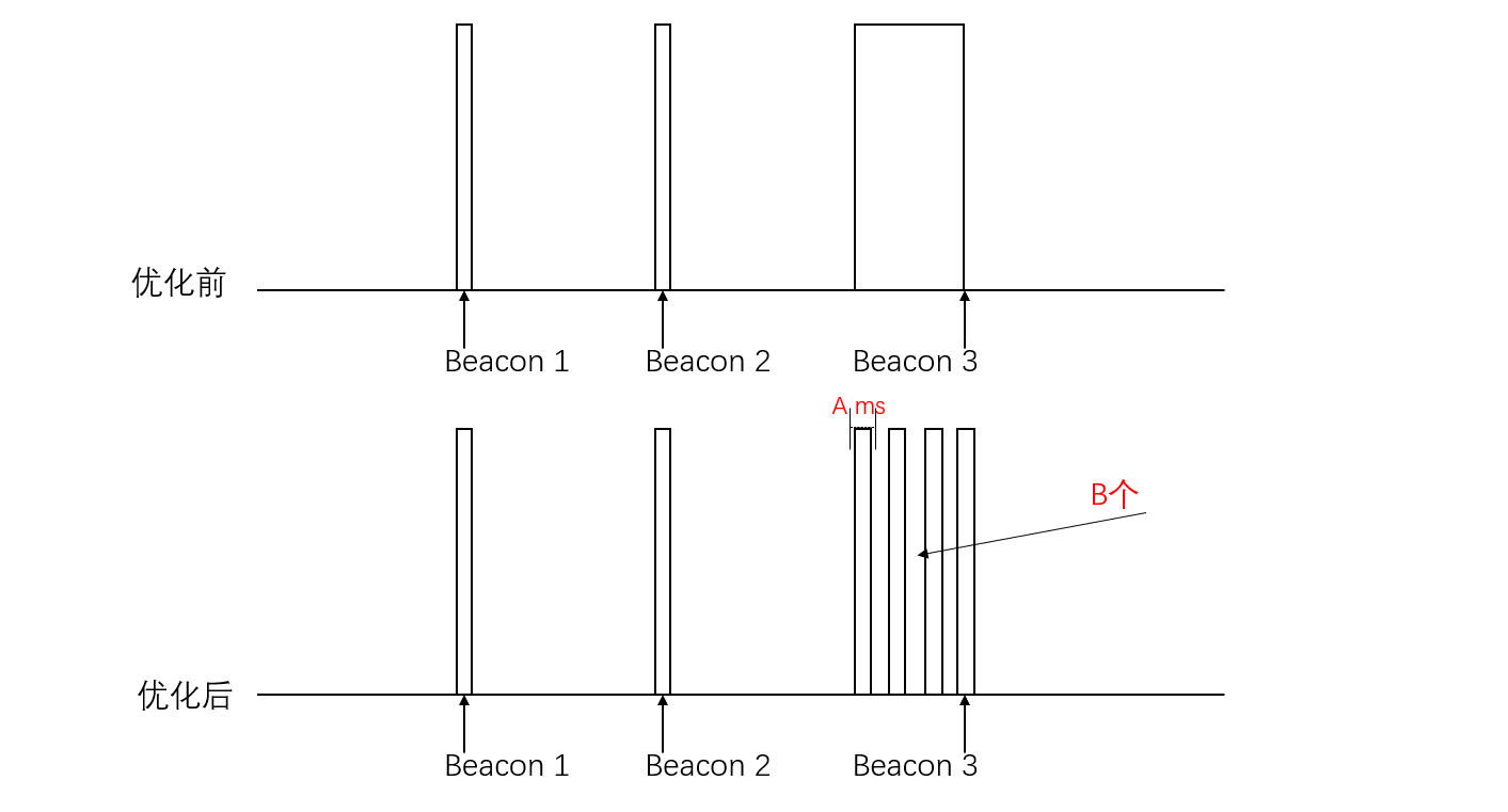
Beacon Lost Optimization Diagram-1
Beacon Lost Optimization Diagram-2
After enabling this option, additional configuration items will be introduced, mainly need to pay attention to:
CONFIG_ESP_WIFI_SLP_Beacon_LOST_TIMEOUT: Indicates how long to wait without receiving Beacon to enter sleep.
CONFIG_ESP_WIFI_SLP_Beacon_LOST_THRESHOLD: Indicates how many times to repeat without receiving before keeping on. This option should not be set too large, generally set to 3 is enough.
Setting Maximum Wi-Fi TX Power
After enabling CONFIG_ESP_PHY_MAX_WIFI_TX_POWER, you can limit the maximum transmission power of Wi-Fi, thereby reducing the instantaneous current and average power consumption during transmission; in scenarios with good signal conditions, it can effectively reduce energy consumption and improve system stability, but it will reduce the communication distance and may affect link reliability, and should be configured according to the actual usage environment.
In the code, you can set it by calling esp_wifi_set_max_tx_power().
Optimizing Wi-Fi Execution Speed
Placing some Wi-Fi related content in IRAM can improve Wi-Fi execution speed. This operation can shorten the active time of RF and CPU, allowing the system to enter Modem sleep or Light sleep mode earlier, thereby reducing the overall average power consumption.
The related configuration items are as follows:
CONFIG_ESP_WIFI_IRAM_OPT: Put frequently called functions in the Wi-Fi library into IRAM for execution.
CONFIG_ESP_WIFI_EXTRA_IRAM_OPT: Put an additional part of frequently called Wi-Fi library functions into IRAM for execution.
CONFIG_ESP_WIFI_SLP_IRAM_OPT: Put functions related to TBTT processing (target Beacon transmission time) and receiving Beacon in the Wi-Fi library into IRAM for execution. Please note that this option overlaps with the previous two in some functions.
CONFIG_ESP_WIFI_RX_IRAM_OPT: Put frequently called receive (RX) related functions in the Wi-Fi library into IRAM for execution.
Wi-Fi Physical Layer Packet Reception
Note
This optimization item is only applicable to ESP32-C6, ESP32-C5, ESP32-C61 chips. And currently, this function cannot be used with Peripheral Power Down at the same time.
After enabling CONFIG_ESP_WIFI_ENHANCED_LIGHT_SLEEP, during Light sleep, the PHY layer automatically receives packets, and Wi-Fi no longer needs the CPU to receive Beacon, only Wi-Fi MAC + Baseband + RF are working to save power consumption.
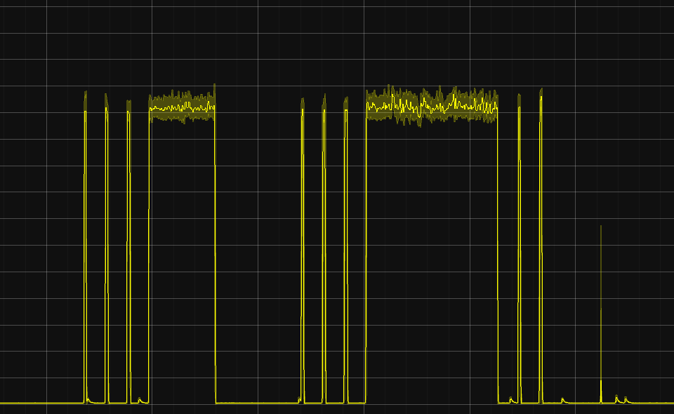
To more intuitively display the working status of various modules in different modes, you can observe the activity differences of CPU, MAC, Baseband, and RF through Waveform diagram of receiving and transmitting under different modes.
Supplementary content
Difference between DTIM and listen interval
When the chip establishes a connection as a STA with the router, it will be informed of the router’s DTIM, that is, how often the router will send a beacon, and the STA needs to wake up at this time to receive the beacon and check if there is information that needs to be processed.
The listen interval, on the other hand, is the STA telling the router how often it needs to wake up to receive the beacon, that is, the former is determined by the router, and the latter can be configured into the chip. The time interval is the value of DTIM or listen interval * 100 MS, if DTIM=10, the wake-up time interval is 10 * 100 ms = 1 s.
External 32 KHz crystal
Using an external 32 KHz crystal can achieve lower power consumption. The main reasons are as follows:
The internal crystal is easily interfered with, and the external crystal has higher precision and can be used in various sleep situations.
For applications with high time accuracy requirements, such as Bluetooth and Wi-Fi keep-alive, it is necessary to wake up regularly to receive Beacon. Once the clock drifts too much and misses the receiving point, it will cause the waiting window period for opening RF to lengthen, thereby greatly increasing power consumption.
There are two types of external crystals:
External 32kHz crystal: It is an external passive crystal, which is also the recommended crystal most of the time
External 32kHz oscillator at 32K_XP pin: It is an external active crystal, which is more expensive and will cause the base current to rise by 50 ~ 100 μA
Enabling the external clock source requires the following configuration:
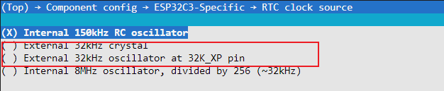
Enable external crystal
Configuration item name:
ESP32C3_RTC_CLK_SRC_EXT_CRYSConfiguration path:
(Top) → Component config → ESP32XX-Specific → RTC clock source
Note
The ESP32-C2 does not have an internal passive crystal oscillation circuit and only supports external active crystals; the layout of the crystal can refer to the hardware design guide corresponding to each chip.
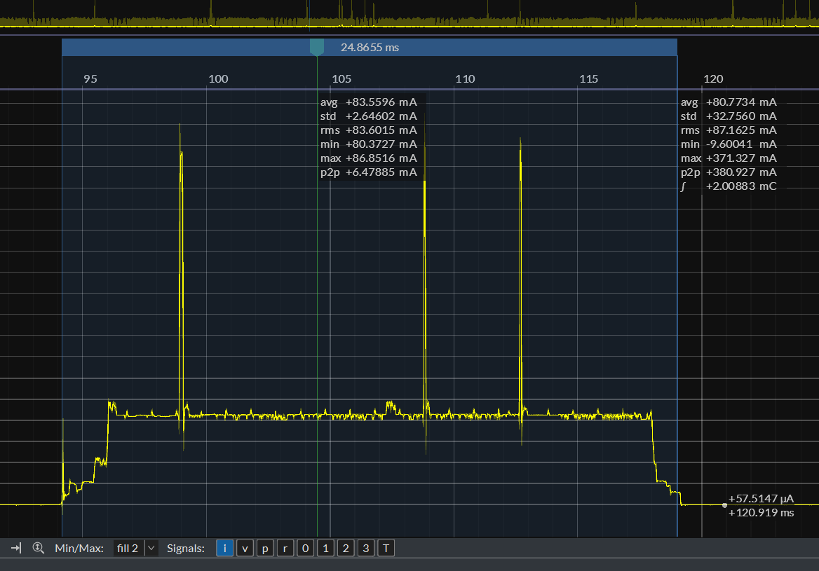
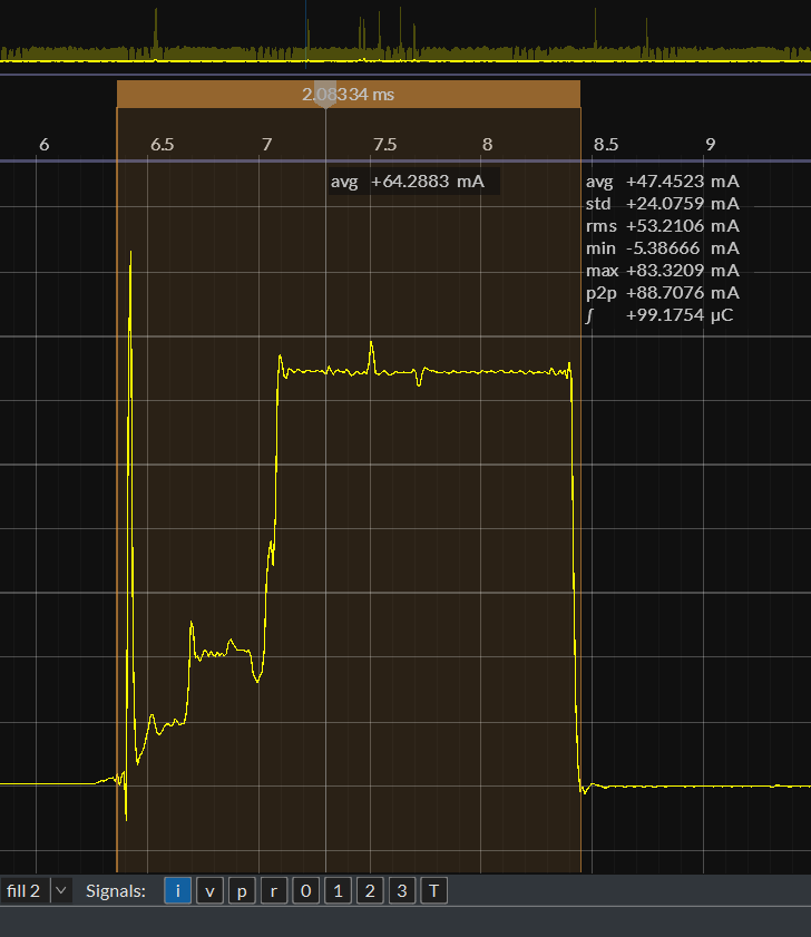
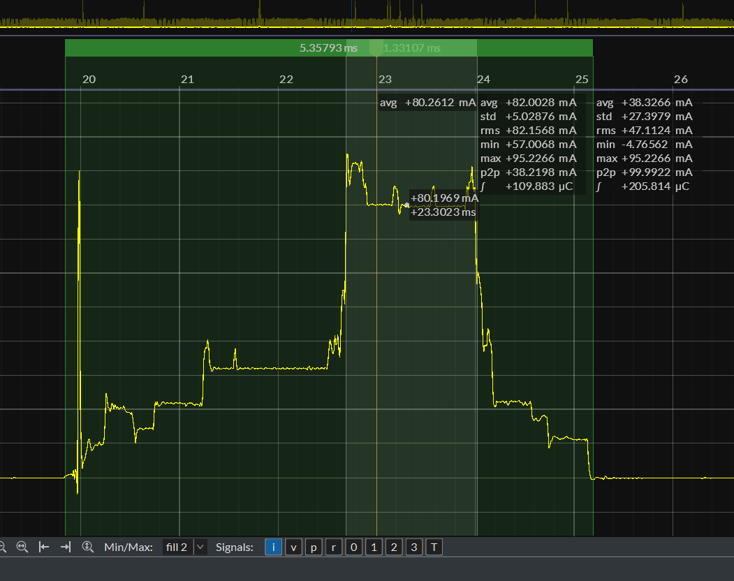
Waveform diagram of receiving and transmitting under different modes
Modem Mode (PHY layer receives Beacon): The time cost of receiving a packet once is about 2.1 ms, and the current of receiving a packet is about 64 mA ~ 70 mA.
Active Mode RX: The duration of receiving a packet is about 5.3 ms, and the current for receiving a packet is about 80 mA.
RX without receiving a packet: Compared to the situation where no packet is received, there will be no current waveform that lasts for a period of time.
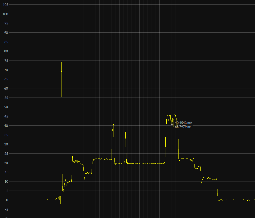
Active Mode TX: The duration is uncertain, and the TX current is related to the Wi-Fi channel.