ESP Low Power Introduction
Note
This document is automatically translated using AI. Please excuse any detailed errors. The official English version is still in progress.
Overview
The ESP32 series chips can be roughly divided into the following five modules according to their functions and power supply domains:
RF Module: That is, the radio frequency module, used for Bluetooth / Wi-Fi transmission and reception (TX / RX) functions.
CPU: Such as Xtensa core (ESP32 / ESP32-S2 / ESP32-S3, etc.), RISC-V core (ESP32-C3 / ESP32-C2, etc.).
Wireless Digital Module: Includes the physical layer of Wi-Fi and Bluetooth, such as Wi-Fi’s MAC, Bluetooth’s Link controller.
Non-RTC peripherals: Such as commonly used SPI, I2C, LEDC, etc.
RTC related: Includes RTC GPIO, ULP, etc.
The power consumption of the chip is mainly determined by the working status of each functional module. Generally, the more modules in the working state, the higher the overall power consumption of the chip.
The ESP32 series chips support four working modes. In order of average power consumption during operation from high to low, they are Active, Modem sleep, Light sleep, and Deep sleep. The power-on and running status of each functional module in different modes are different, resulting in power consumption differences. The following figure shows the running status of each module in different working modes:
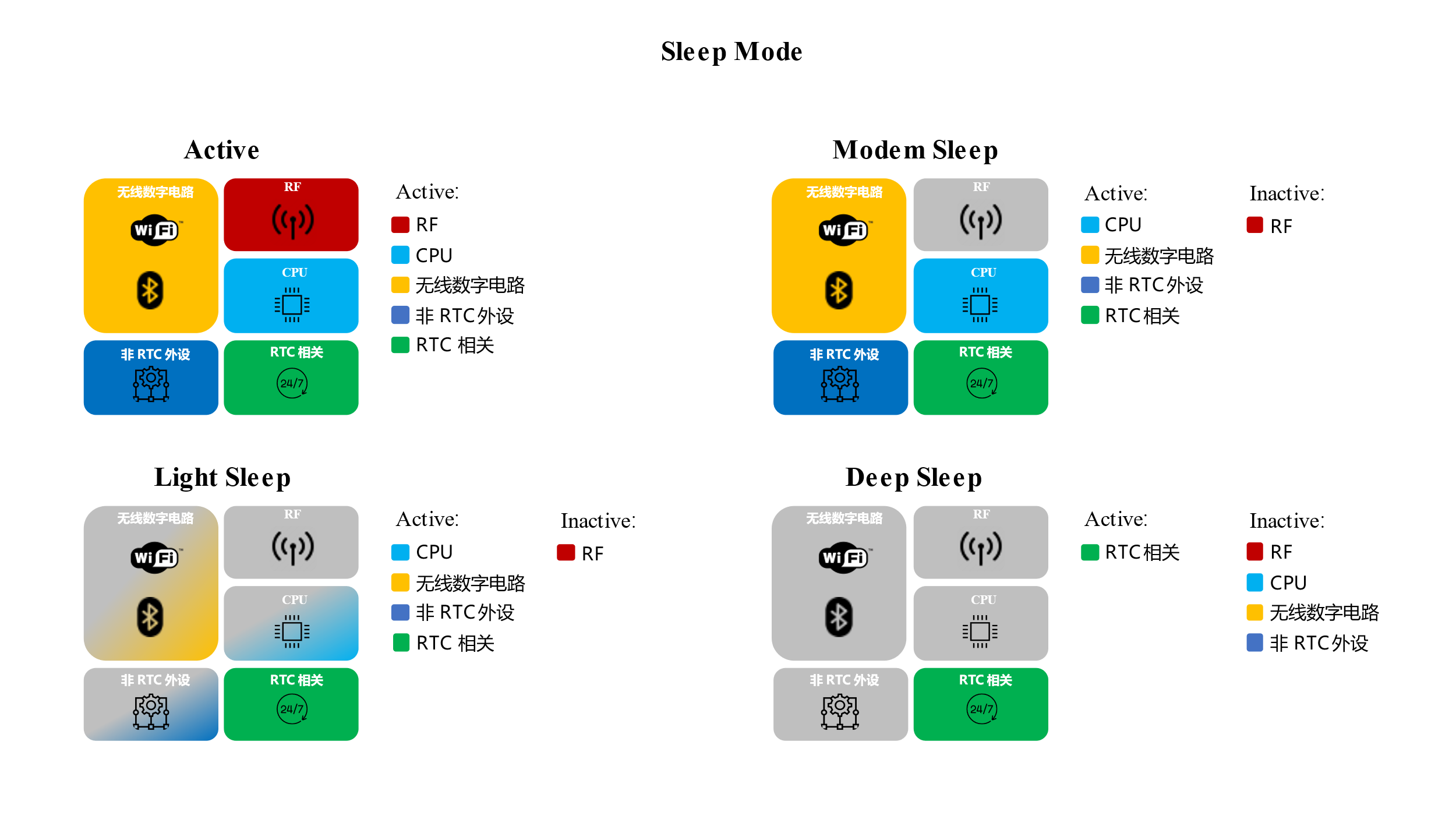
Active Mode
In this mode, all modules of the chip are in the power-on working state, and the quiescent current of the chip is about 20 ~ 40 mA.
Modem Sleep Mode
In Modem sleep mode <https://docs.espressif.com/projects/esp-idf/en/latest/esp32/api-guides/low-power-mode/low-power-mode-wifi.html#modem-sleep>, when the wireless module has no data transmission tasks or does not perform scanning, the RF radio frequency module will automatically shut down to reduce power consumption, while the CPU continues to run, and the chip can still handle application tasks. The quiescent current of the chip can refer to the power consumption parameters in the datasheet of each model.
You can use the hello_world example to test the power consumption data in Modem sleep mode.
Light Sleep Mode
In Light sleep mode <https://docs.espressif.com/projects/esp-idf/en/latest/esp32/api-guides/low-power-mode/low-power-mode-soc.html#light-sleep>, digital peripherals, CPU, and most of the RAM use clock gating, and their supply voltage is reduced, and the RF module will be turned off to achieve the result of reducing power consumption. The quiescent current of the chip at this time can refer to the power consumption on the datasheet of each chip, such as ESP32-C3 is 130 μA, ESP32-S3 is 240 μA.
Note
In ESP-IDF, a light_sleep example is provided, but this example is only for demonstrating the usage of related APIs. If you want to test the power consumption data in Light sleep mode, it is recommended to enable the Automatic Light sleep configuration item.
Deep sleep mode
In Deep sleep mode, all modules except the RTC module are powered down. The base current can refer to the datasheet of each chip, such as ESP32-C3 is 5 μA, ESP32-S3 is 7 μA.
Wake-up source
Chips in Light sleep and Deep sleep states can be awakened by wake-up sources. The Light sleep and Deep sleep wake-up sources of different chips are shown in the table below. The specific use of each wake-up source can be found in the Light sleep and Deep sleep examples and the Wake-up source section in the IDF programming guide.
ESP32 |
ESP32-S2 |
ESP32-S3 |
ESP32-C3 |
ESP32-C2 |
ESP32-C6 |
ESP32-C5 |
ESP32-C61 |
ESP32-H2 |
ESP32-P4 |
|
|---|---|---|---|---|---|---|---|---|---|---|
RTC Timer |
√ |
√ |
√ |
√ |
√ |
√ |
√ |
√ |
√ |
√ |
GPIO |
√ |
√ |
√ |
√ |
√ |
√ |
√ |
√ |
√ |
√ |
EXT0 (Only RTC GPIO) |
√ |
√ |
√ |
|||||||
EXT1 (Only RTC GPIO) |
√ |
√ |
√ |
√ |
√ |
√ |
√ |
√ |
||
UART |
√ |
√ |
√ |
√ |
√ |
√ |
√ |
√ |
√ |
√ |
Touch |
√ |
√ |
√ |
√ |
||||||
ULP-FSM |
√ |
√ |
√ |
|||||||
ULP-RISCV/LP core |
√ |
√ |
√ |
√ |
√ |
ESP32 |
ESP32-S2 |
ESP32-S3 |
ESP32-C3 |
ESP32-C2 |
ESP32-C6 |
ESP32-C5 |
ESP32-C61 |
ESP32-H2 |
ESP32-P4 |
|
|---|---|---|---|---|---|---|---|---|---|---|
Timer |
√ |
√ |
√ |
√ |
√ |
√ |
√ |
√ |
√ |
√ |
GPIO (Only RTC GPIO) |
√ |
√ |
√ |
√ |
√ |
√ |
||||
EXT0 (Only RTC GPIO) |
√ |
√ |
√ |
|||||||
EXT1 (Only RTC GPIO) |
√ |
√ |
√ |
√ |
√ |
√ |
√ |
√ |
||
Touch |
√ |
√ |
√ |
√ |
||||||
ULP-FSM |
√ |
√ |
√ |
|||||||
ULP-RISCV/LP core |
√ |
√ |
√ |
√ |
√ |
Notes
EXT0 and EXT1 wake-ups can only act on RTC GPIO. Compared with GPIO wake-up, they depend on different hardware power domains, but the actual usage experience is not much different.
UART interrupt requires a certain number of bytes for wake-up, so if you want to use UART interrupt, you need to agree on the wake-up rules. For more explanations, please refer to UART wake-up.
In Deep sleep mode, GPIO wake-up needs to use RTC GPIO.
Except for GPIO, the wake-up sources of Deep Sleep are similar to Light Sleep, but ULP (coprocessor) wake-up is added. ESP32 only supports ULP-FSM, which needs to be written in assembly language; while ESP32-S2/S3 supports ULP-RISCV, which can be written in C language.