Measuring Development Board Power Consumption
Note
This document is automatically translated using AI. Please excuse any detailed errors. The official English version is still in progress.
Test Description
Power consumption is a significant factor affecting product development. However, in the early stages of development, developers may measure inaccurately or use incorrect configurations, leading to significant deviations from the datasheet, affecting preliminary evaluations.
This document aims to help developers quickly and accurately conduct preliminary power consumption measurements.
The entire measurement process mainly includes two aspects:
Hardware wiring during measurement
Software-related configurations
When evaluating low-power applications, it is recommended to directly test the module with flying wires. For the method of module power consumption testing, please refer to Measuring Module Power Consumption. If the development board is used directly for measurement, the measured current will usually be larger than the datasheet.
If it is necessary to use the development board for measurement, the development board can be handled in the following ways to obtain data closer to the actual power consumption.
Development Board Jumper Cap Removal Test
For the ESP32-C6 and later series of development boards, including ESP32-C6, ESP32-H2, ESP32-C5, ESP32-C61, etc., a jumper cap position is reserved on the board, and current measurement can be performed by removing the jumper cap.
Take ESP32-C6-DevKitC-1 as an example.
Step 1: Remove the jumper cap on the front of the development board
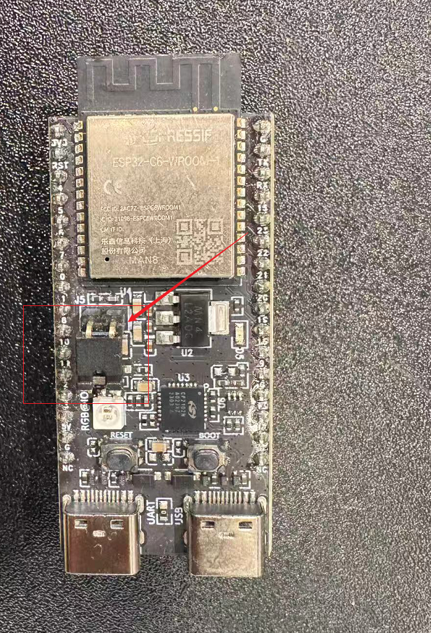
Jumper cap position schematic
Step 3: The development board continues to use USB power supply, and the two ends of the ammeter can be connected to the two pins at the original position of the jumper cap to measure the current passing through the module.
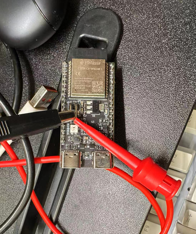
Wiring schematic
Development Board Line Cutting Test
For development boards without jumper caps, including ESP32, ESP32-S2, ESP32-S3, ESP32-C3, ESP8684 series, etc., the following method can be used.
Step 1: Cut off the current path on the back of the development board, usually the thickest line.
Line cutting schematic
Step 2: Fly a wire out at the power chip on the front of the development board.
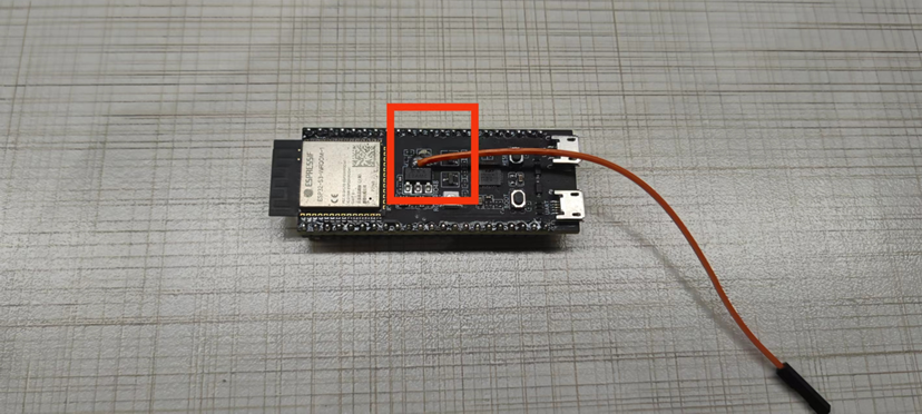
Flying wire schematic
Step 3: The development board continues to use USB power supply, and the two ends of the ammeter can be connected to the drawn wire and the 3V3 pin on the development board to measure the current passing through the module.
Wiring schematic
Development Board Resistor Removal Test
Using ESP32-S3-DevKitC-1 as an example.
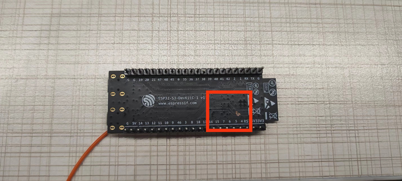
Step 1: Remove the R24 (0 ohm resistor) on the front.
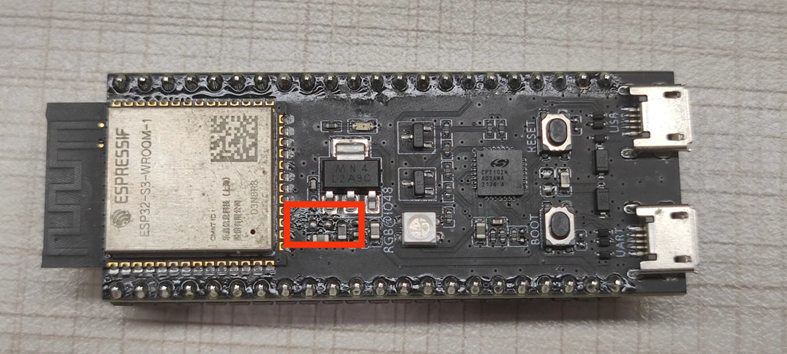
Physical image of resistor removal
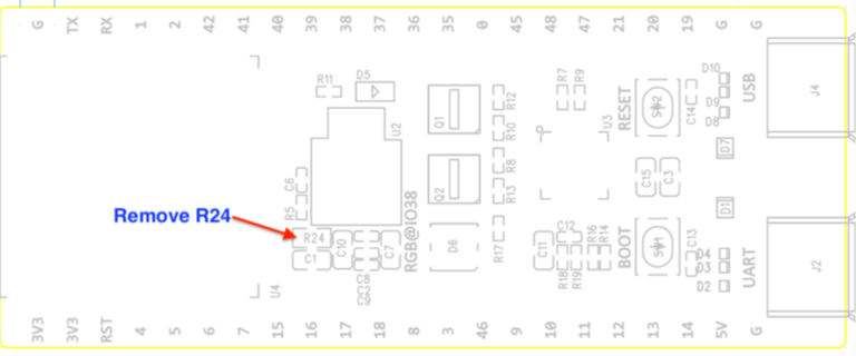
Schematic diagram of resistor removal
Step 2: After removing the resistor, connect one end of the ammeter to the 3V3 DC source input, the other end to the 3V3 pin of the development board, and connect the GND of the development board to the GND of the DC input source, as shown in the following wiring diagram:
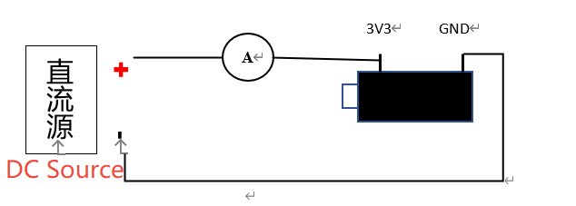
Schematic diagram of wiring after resistor removal
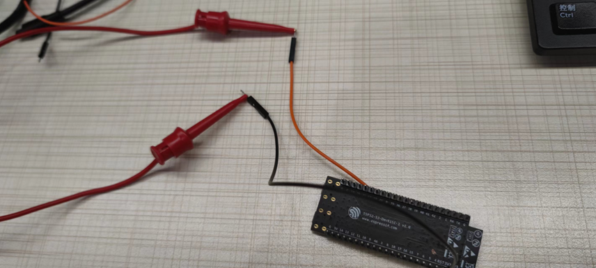
The following is a physical connection diagram using another ESP32 as a DC source:
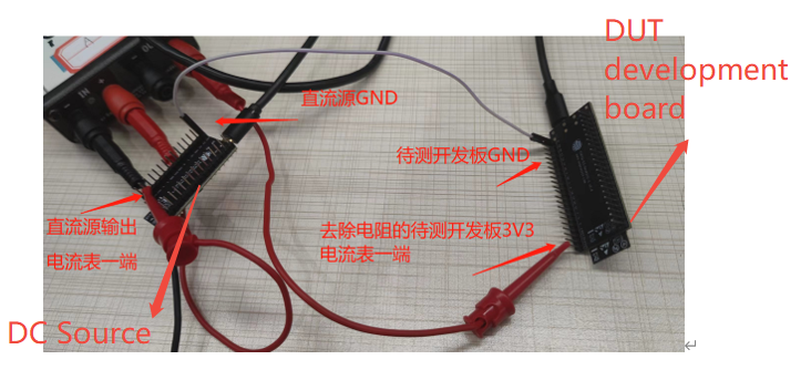
Physical connection diagram after resistor removal
Summary
For applications that need to connect an external crystal, since the development board itself does not have a crystal interface, if you want to do a simple test, you can solder a crystal to the pins
XTAL_32K_PandXTAL_32K_Nmarked in the datasheet.Be careful when testing the cut line to avoid cutting other circuits.
The current method of removing resistors is only suitable for larger development boards:
Supported: ESP32 / ESP32-S2 / ESP32-S3
Not supported: ESP32-C3 / ESP8684 (no R24 0 ohm resistor)
Do not use USB power supply when measuring with the resistor removal method, the UART port may introduce additional power interference.