ESP Video Application Development Guide
Overview
The esp_video component provides video capture and image processing for Espressif ESP32 series chips. This component implements some of the functionality defined by the Linux V4L2 (Video for Linux Two) specification, encapsulates low-level implementations such as camera sensor drivers, the ISP (Image Signal Processor), and hardware codecs, and exposes unified device nodes, such as /dev/video0, to upper layers. Applications can follow the common V4L2 capture flow, reducing platform adaptation costs.
The main design characteristics are as follows:
Standards compliance: The API follows a subset of the V4L2 specification and supports common ioctls, request codes, and buffer streaming, which makes it easier to migrate and reuse existing Linux applications.
Layered architecture: The upper layer provides standard application interfaces, the middle layer is responsible for device management and buffer control, and the lower layer connects to hardware drivers and responds to callbacks, making it easier to extend support to a variety of camera sensors.
Efficient queues: Multiple buffer queues are supported, including MMAP, USERPTR, and other modes, for high-frame-rate, low-latency capture.
Flexible adaptation: The underlying HAL (Hardware Abstraction Layer) adapts, in a plug-in manner, to different camera sensors, ISP modules, and codec modules, covering a variety of ESP32 series chips.
Easy to build on: Interfaces, structures, and return codes follow V4L2 and industry practice, and the memory and performance trade-offs suit embedded platforms.
This guide introduces, in reading order, the software architecture, hardware capabilities and device nodes, the data path, and project integration and application programming. For ioctl request codes and command parameters, see Commands. For initialization APIs, see API Reference.
Software Architecture
esp_video uses a layered design: the application accesses device nodes through V4L2 ioctls; the middle layer performs device management, format negotiation, and buffer queuing; the lower layer connects, through the HAL, to MIPI-CSI, DVP, SPI, USB, ISP, and hardware codec drivers. The layered structure is shown in the figure below.
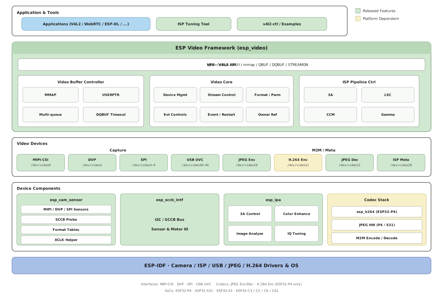
esp_video Layered Architecture
Hardware and Device Nodes
Chips and Peripherals
The camera interfaces and codec peripherals available on each chip are as follows. Whether a given device can actually be used also depends on whether the corresponding option is enabled in menuconfig.
SoC |
MIPI-CSI |
DVP |
SPI |
JPEG Encoder |
JPEG Decoder |
H.264 Encoder |
ISP |
USB |
|---|---|---|---|---|---|---|---|---|
ESP32-P4 |
Y |
Y |
Y |
Y |
Y |
Y |
Y |
Y |
ESP32-S31 |
N |
Y |
Y |
Y |
Y |
N |
N |
Y |
ESP32-S3 |
N |
Y |
Y |
N |
N |
N |
N |
Y |
ESP32-C3 |
N |
N |
Y |
N |
N |
N |
N |
N |
ESP32-C5 |
N |
N |
Y |
N |
N |
N |
N |
N |
ESP32-C6 |
N |
N |
Y |
N |
N |
N |
N |
N |
ESP32-C61 |
N |
N |
Y |
N |
N |
N |
N |
N |
Note
When the ISP is enabled, MIPI-CSI supports input images in RAW8/RAW10 format and output images in RAW8/RGB888/RGB565/YUV420/YUV422(UYVY) format. When the ISP is disabled, MIPI-CSI directly outputs the image produced by the camera sensor.
ESP32-P4 v3.0 and later chips add image format conversion inside the MIPI-CSI module, which can convert input RGB888/RGB565/YUV420/YUV422(UYVY/YUYV/VYUY/YVYU) into the same class of formats listed above.
An SPI camera can receive images with only 3 pins: V-SYNC, PCLK (Pixel Clock), and Data. To increase the frame rate and resolution, increase the Data bit width (for example, to 2 or 4 bits). That also uses more pins. After
ESP_VIDEO_ENABLE_THE_SECOND_SPI_VIDEO_DEVICEis enabled, the second SPI device/dev/video4is available.The JPEG hardware encoder and decoder are available on chips with an integrated JPEG codec (ESP32-P4 and ESP32-S31). The H.264 hardware encoder is available only on ESP32-P4. An H.264 hardware decoder device is not provided currently.
On ESP32-P4 ECO3 and later, the JPEG hardware encoder additionally supports
V4L2_PIX_FMT_YUV420andV4L2_PIX_FMT_YUV444; the JPEG hardware decoder additionally supportsV4L2_PIX_FMT_YUV420. The decoder also supports swapping the RGB channel order, and can therefore output BGR565/BGR888.
Device Nodes
esp_video manages MIPI-CSI, DVP, SPI, USB, the JPEG/H.264 codecs, and the ISP through device nodes (file descriptors). In the table below, Capture means a capture device, M2M means a Memory-to-Memory video codec device, and Meta means a metadata device.
Hardware |
Video Device |
Type |
Input Format |
Output Format |
|---|---|---|---|---|
MIPI-CSI |
/dev/video0 |
Capture |
/ |
Sensor output format, or the format after ISP processing |
DVP |
/dev/video2 |
Capture |
/ |
Sensor output format |
SPI (0–1) |
/dev/video3–4 |
Capture |
/ |
Sensor output format |
USB UVC (0–9) |
/dev/video40–49 |
Capture |
/ |
Sensor output format |
JPEG Hardware Encoder |
/dev/video10 |
M2M |
RGB565/RGB888/YUV422(UYVY)/Gray8/YUV420/YUV444 |
JPEG ( |
H.264 Hardware Encoder |
/dev/video11 |
M2M |
YUV420 ( |
H.264 ( |
JPEG Hardware Decoder |
/dev/video12 |
M2M |
JPEG ( |
RGB565/BGR565/RGB888/BGR888/YUV422(UYVY)/Gray8/YUV420/YUV444 |
ISP |
/dev/video20 |
Meta |
Sensor output format |
Metadata ( |
Data Path
Image data can be read directly from a Capture device, or sent to an M2M device for encoding or decoding. Buffer queues run through the whole path. A camera sensor that outputs RAW also needs the ISP and IPA (Image Processing Algorithms) for real-time closed-loop control.
Capture Devices and M2M Devices
A Capture device captures images from the camera interface. The component also supports M2M devices: the application sends a buffer into one end of the codec and takes the encoded or decoded data from the other end. Node paths and pixel formats are in the table in the previous section.
The hardware codecs include:
JPEG encoder (
/dev/video10): Compresses RGB/YUV into JPEG.H.264 encoder (
/dev/video11, ESP32-P4 only): Compresses YUV420 into H.264.JPEG decoder (
/dev/video12): Decompresses JPEG into RGB/YUV. Use it for USB UVC MJPEG streams, for decoding stored files, and for a pipeline that decodes JPEG and then encodes H.264.
Typical steps for encoding through an M2M device:
Call
DQBUFon the Capture device to obtain the frame buffer that holds the sensor data.Feed that buffer, through
QBUF, into the OUTPUT (input) queue of the M2M encoder.The M2M device passes the input to the encoder.
After encoding completes, the result enters the CAPTURE (output) queue of the M2M device.
Call
DQBUFon the M2M device to take out the encoded data.
The decoding flow is similar, except that the input is a JPEG bitstream and the output is a pixel format:
Call
QBUFto send the JPEG data to the OUTPUT queue of the JPEG decode device.After decoding completes, call
DQBUFon the JPEG decode device to retrieve the RGB/YUV image from the CAPTURE queue.
**********************   YUV/RGB    ********       *************
* Encoder            * <----------- * V4L2 * <---- * Program   *
* (JPEG/H.264)       * -----------> * M2M  * ----> *           *
**********************  JPEG/H.264  ********       *************

**********************    JPEG      ********       *************
* Decoder            * <----------- * V4L2 * <---- * Program   *
* (JPEG)             * -----------> * M2M  * ----> *           *
**********************   YUV/RGB    ********       *************
Buffer Queues
The video buffer manager keeps a buffer queue for each device. An application reads images by repeatedly enqueuing (QBUF) and dequeuing (DQBUF) buffers:
*************************************************
*                  Application                  *
*************************************************
   |                                       ^
   | Enqueue (QBUF)                        | Dequeue (DQBUF)
   v                                       |
 ********    ********     ********    ********
 * buf  *--->* buf  *---> * buf  *--->* buf  *
 ********    ********     ********    ********
Two types of buffers are commonly used in the system:
Capture: Receives the captured result. For an M2M encoder, this is the encoded bitstream; for the JPEG decoder, this is the decoded pixel data.
Output: Feeds an image into the encoder input, or feeds a JPEG bitstream into the decoder input.
When an M2M encoder is used, the two types of buffers work with QBUF/DQBUF as follows:
**********  DQBUF
* cap_fd * --------> Dequeue filled raw image buffer from cap_fd receive queue
**********                                                                     |
*                                                                              |
*                                                                              v
*                                                                      QBUF **********
* Enqueue raw buffer to m2m_fd OUTPUT queue    <--------------------------- * m2m_fd *
* |                                                                         **********
* |
* v
**********  DQBUF
* m2m_fd * -------> Dequeue the encoded image data from the CAPTURE queue of m2m_fd
**********
ISP Real-Time Control
When light, contrast, or color temperature changes, the ISP pipeline and the camera sensor parameters need to be updated accordingly. esp_video adjusts the parameters of each sub-device according to scene changes. A typical data flow is as follows:
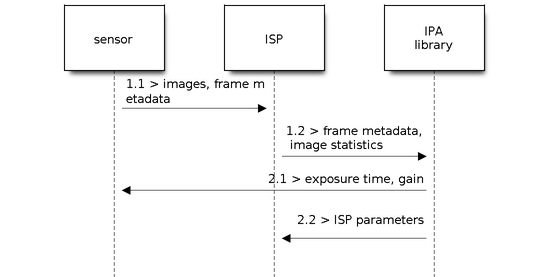
esp-ipa Control Loop
Statistics stage
1.1: The camera sensor sends the image to the ISP.
1.2: The ISP generates brightness and color statistics from the image and sends them to the IPA.
Control dispatch stage
2.1: The IPA sends brightness controls such as exposure and gain to the sensor according to the statistics.
2.2: The IPA sends brightness and color parameters to the ISP based on the statistics.
How to Use esp_video
Add the Component
Run idf.py add-dependency "espressif/esp_video=*" in the project directory. For more information, see IDF Component Manager.
Initialization Configuration
Configure the initialization parameters in the application, and then call esp_video_init(). This API probes the devices on the bus and loads the default configuration. For the complete parameter description, see API Reference.
#include "linux/videodev2.h"
#include "esp_video_device.h"
#include "esp_video_init.h"
#include "esp_video_ioctl.h"

static const esp_video_init_config_t s_cam_config = {
    .csi       = &s_csi_config,
    .cam_motor = &s_cam_motor_config,
    .dvp       = &s_dvp_config,
    .spi       = &s_spi_config,
};
/* Configure pins such as xclk, reset, and pwdn according to the camera sensor requirements */
...
const esp_video_init_config_t *cam_config_ptr = &s_cam_config;
esp_video_init(cam_config_ptr);
Attention
For a camera sensor that outputs RAW, also check the IPA configuration files in the sensor/cfg directory to make sure the algorithm parameters can be loaded correctly.
Application Programming
The application operates devices through POSIX open/close and V4L2 ioctl. The typical sequence is: open the device -> (optional) query capabilities and formats -> request and queue buffers -> STREAMON -> loop DQBUF/QBUF -> STREAMOFF -> close the device. An M2M device must request buffers and start and stop streaming separately for OUTPUT and CAPTURE. For request codes and command parameters, see Commands.
The following figure shows how the ioctl calls relate to each other:
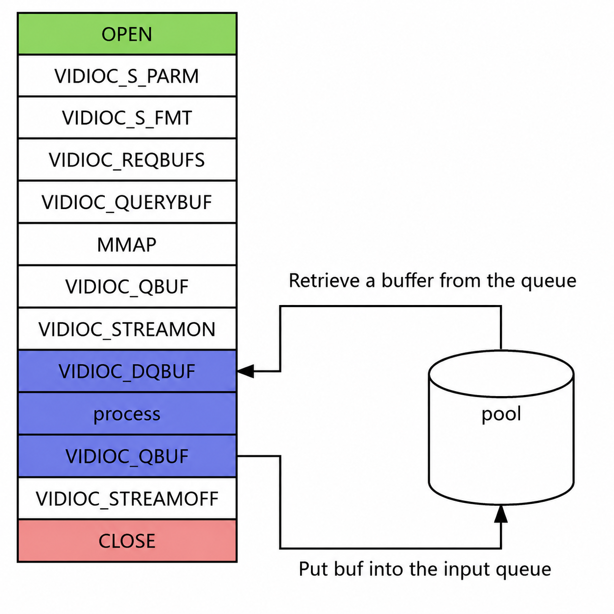
ioctl Interface Programming Model
Open and close the device
#include "esp_video_device.h"

/* Device names are defined in esp_video_device.h */
int fd = open(ESP_VIDEO_MIPI_CSI_DEVICE_NAME, O_RDWR);
...
close(fd);
Query device capabilities (optional)
ioctl(fd, VIDIOC_QUERYCAP, &capability);
if (capability.capabilities & V4L2_CAP_VIDEO_OUTPUT) {
    printf("Display capability is supported\n");
}
Query and set the data format (optional)
/* Enumerate supported formats */
ioctl(fd, VIDIOC_ENUM_FMT, &fmtdesc);

/* Query the current format */
ioctl(fd, VIDIOC_G_FMT, &default_format);

/* Set the format */
ioctl(fd, VIDIOC_S_FMT, &format);
Attention
During probing, the device loads the default format from the configuration menu. Changing the format at runtime must be done while streaming is stopped. For a custom format, see the example
esp_video/examples/video_custom_format.Buffer queue and data stream
/* Request buffers */
ioctl(fd, VIDIOC_REQBUFS, &req);

/* Query the buffer to obtain the offset that can be mapped */
ioctl(fd, VIDIOC_QUERYBUF, &buffer);

/* addr is an address accessible from user space */
uint8_t *addr;
addr = mmap(NULL, buffer.length, PROT_READ | PROT_WRITE, MAP_SHARED,
            fd, buffer.m.offset);

/* Put the buffer into the queue and wait for it to be filled */
if (ioctl(fd, VIDIOC_QBUF, &buf) != 0) {
    ESP_LOGE(TAG, "failed to queue video frame");
    close(fd);
    return -1;
}

/* Start streaming */
if (ioctl(fd, VIDIOC_STREAMON, &type) != 0) {
    ESP_LOGE(TAG, "failed to start stream");
    close(fd);
    return -1;
}

/* Take out the filled buffer */
if (ioctl(fd, VIDIOC_DQBUF, &buf) != 0) {
    ESP_LOGE(TAG, "failed to receive video frame");
    close(fd);
    return -1;
}

/* Stop streaming */
if (ioctl(fd, VIDIOC_STREAMOFF, &type) != 0) {
    ESP_LOGE(TAG, "failed to stop stream");
    close(fd);
    return -1;
}
Application Examples
The repository examples listed below complement the Data Path and Buffer Queues sections above.
capture_stream demonstrates how to open a video device and capture images.
m2m demonstrates how to perform three kinds of processing through an M2M device: hardware JPEG/H.264 encoding after capture, hardware decoding of a JPEG bitstream, and JPEG decoding followed by H.264 encoding.
image_storage demonstrates how to store images and video streams to an SD card or flash.
simple_video_server demonstrates how to set up a local server so that images can be previewed and downloaded in a browser.
uvc demonstrates how to output the camera picture to a PC over USB.
v4l2_cmd demonstrates how to control a V4L2 video device with commands similar to v4l2-utils.
video_custom_format demonstrates how to initialize the video system with a custom format description.