Display and Touch Panel
The ESP32-S2-HMI-DevKit-1 has a 4.3-inch color TFT-LCD with 800×480 resolution, and a touch panel with an I2C interface. The interface type and data bit width of this display is controlled by programmable pins. This development board has been configured as 16-bit 8080 parallel communication via resistors.
This LCD uses RM68120 as its display IC and FT5436 as its touch IC.
Communication
The display IC of the LCD used in ESP32-S2-HMI-DevKit-1 has been configured for 16-bit 8080 parallel communication, with a total of 18 GPIOs used, i.e., 16 data lines (LCD_D0…LCD_D15), a bit clock signal (LCD_WR) and a data/command distinguish signal (LCD_DC/LCD_RS).
The touch IC uses the I2C interface to communicate with MCU and can share this interface with other I2C’s ICs, and thus does not need to use additional GPIOs. The touch IC supports interrupt signal output. The interrupt signal is first sent to the P2 pin of the IO expander, and the falling edge from this pin will generate a low level in the interrupt output pin of the IO expander, so that the MCU receives this interrupt signal. In this case, you can read the input level register of the IO expander to check whether this interrupt is from the touch IC. Once a read operation completed, the interrupt flag will be cleared.
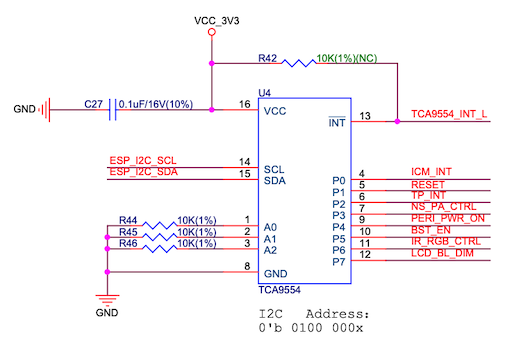
ESP32-S2-HMI-DevKit-1 IO expander schematic
Backlight
As the LEDs are connected in series, they need to be drived by constant current via the Booster circuit. The rated current is 18 mA and the voltage is approximately 24 V (may not be accurate, only for reference). To prevent the feedback voltage of the Booster circuit always being 0 when the display is not connected, and thus causing high voltage loaded to both ends of the backlight filter capacitor C21, please make sure this capacitor can withstand 38 V.

ESP32-S2-HMI-DevKit-1 backlight PWM dimming schematic (click to enlarge)
Since PWM dimming may cause display flicker and some Booster IC do not support high-frequency PWM signal control, this development board provides an option to use DC dimming circuit to reach high performance, as shown in the figure below:
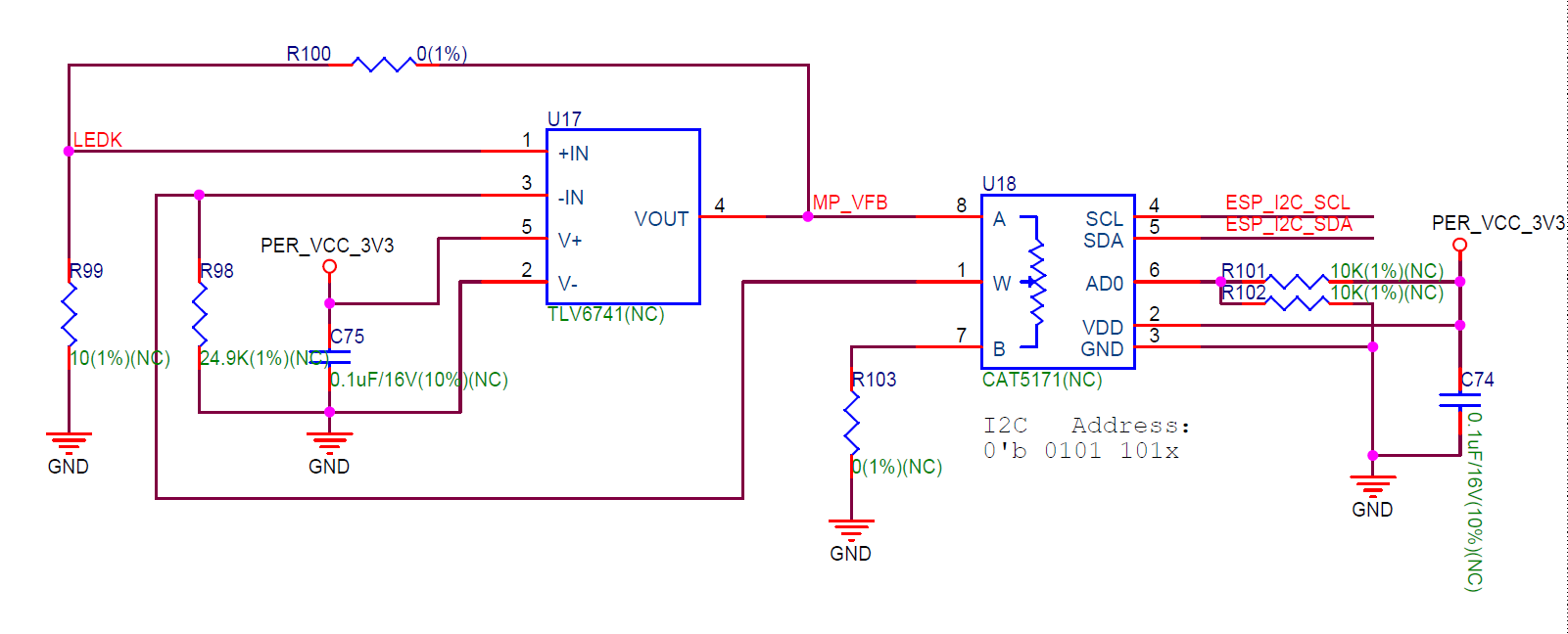
ESP32-S2-HMI-DevKit-1 DC dimming circuit schematic (click to enlarge)
This DC dimming circuit inputs the VFB voltage to the operational amplifier TLV6741, whose gain resistor is a digital potentiometer that can be modified via the I2C bus. This digital potentiometer is CAT5171, with 256 levels of resolution and a maximum resistance value of 50 kOhm.
The EN pin of the Booster IC is controlled by the P7 pin of the IO expander in high level. If you want to keep the contents while turning off the display, please set this pin to low level so as to disable backlight.
Touch
The capacitive touch panel on the development board uses a touch IC with a resolution of 800×480 and supports up to 5-point touch and hardware gesture recognition.
The hardware of this display IC does not support screen rotation itself. Therefore, for scenarios where the panel is needed to be rotated, you may need to convert the data read by the touch IC through calculating its relative value to the resolution or via certain software. Multi-touch is supported by hardware and we provide some APIs for reading the multiple touch points. However, since the LVGL used in the GUI library does not support multi-touch processing for now, you may need to handle the data of these touch points in the application layer yourself.