MCPWM Generator: Create the PWM Waveform
The generator is the final digital output. It does not have a fixed duty-cycle setting; instead, you teach it what level to drive at timer and comparator events. This makes simple PWM easy and leaves room for asymmetric, complementary, and phase-sensitive waveforms.
This is one of the biggest differences from a simpler PWM peripheral: MCPWM does not just ask for frequency and duty, it lets you describe what should happen at each important event. That adds concepts up front, but gives much tighter control over waveform structure.
Your first PWM output
This is the completion of the timer/operator/comparator setup in the preceding pages. At timer zero, drive the GPIO high. When the comparator reaches 15, drive it low. With a 50-tick period, the output is high for 15 ticks (30%).
Application: basic single-output PWM
Use this for the simplest single-output PWM cases, such as an RC servo control signal, LED dimming, or a basic duty-controlled output where polarity and protection are already handled elsewhere.
mcpwm_gen_handle_t generator = NULL;
mcpwm_generator_config_t gen_config = { .gen_gpio_num = 18 };
ESP_ERROR_CHECK(mcpwm_new_generator(oper, &gen_config, &generator));

ESP_ERROR_CHECK(mcpwm_generator_set_action_on_timer_event(
    generator, MCPWM_GEN_TIMER_EVENT_ACTION(
        MCPWM_TIMER_DIRECTION_UP, MCPWM_TIMER_EVENT_EMPTY,
        MCPWM_GEN_ACTION_HIGH)));
ESP_ERROR_CHECK(mcpwm_generator_set_action_on_compare_event(
    generator, MCPWM_GEN_COMPARE_EVENT_ACTION(
        MCPWM_TIMER_DIRECTION_UP, comparator, MCPWM_GEN_ACTION_LOW)));
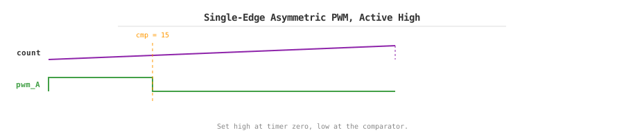
Up-counting, active-high PWM: set high at zero and low at compare.
The generator configuration is small:
gen_gpio_num— the GPIO that carries the PWM output. A second generator in the same operator, configured with the same actions, drives a second pin from the same time base.invert_pwm— inverts the PWM signal through the GPIO matrix. This is a hardware inversion of the final output, distinct from changing the actions; choose one of the two, not both.
Action configuration
The configuration names say exactly what happens: MCPWM_GEN_ACTION_HIGH, MCPWM_GEN_ACTION_LOW, or MCPWM_GEN_ACTION_TOGGLE at a particular event. The helper macros make the three important choices visible at the call site — direction, event source, and output level.
For an up-counting timer, MCPWM_TIMER_EVENT_EMPTY is the zero boundary and MCPWM_TIMER_EVENT_FULL fires at the timer peak. In up-counting mode the peak equals the period, so FULL lands on the period boundary; in up-down mode the peak is period_ticks / 2, so FULL lands in the middle of the cycle. A compare action uses the comparator's threshold. The first example therefore means "start the cycle high; end the active part when the count reaches 15." A compare value outside the timer range never produces its event.
Every action must specify a timer direction, even though the choice only makes a visible difference in up-down mode. In up-counting mode the counter only runs upward, so the action configured for MCPWM_TIMER_DIRECTION_UP is the one that fires — you still have to write it explicitly. In up-down mode, configure actions for both MCPWM_TIMER_DIRECTION_UP and MCPWM_TIMER_DIRECTION_DOWN when both edges matter. This is what turns one comparator into a center-aligned PWM.
Classic Waveform Examples
The examples below build on the first PWM output from the previous section, reusing the same timer, operator, and comparator objects to create other common waveforms.
Invert the active polarity
Some gate drivers and LEDs are active low, such as a low-active gate-driver enable, an inverted LED path, or a board-level interface that is already inverted. Instead of adding GPIO inversion, set low at the period boundary and high at the comparator:
ESP_ERROR_CHECK(mcpwm_generator_set_action_on_timer_event(
    generator, MCPWM_GEN_TIMER_EVENT_ACTION(
        MCPWM_TIMER_DIRECTION_UP, MCPWM_TIMER_EVENT_FULL, MCPWM_GEN_ACTION_LOW)));
ESP_ERROR_CHECK(mcpwm_generator_set_action_on_compare_event(
    generator, MCPWM_GEN_COMPARE_EVENT_ACTION(
        MCPWM_TIMER_DIRECTION_UP, comparator, MCPWM_GEN_ACTION_HIGH)));
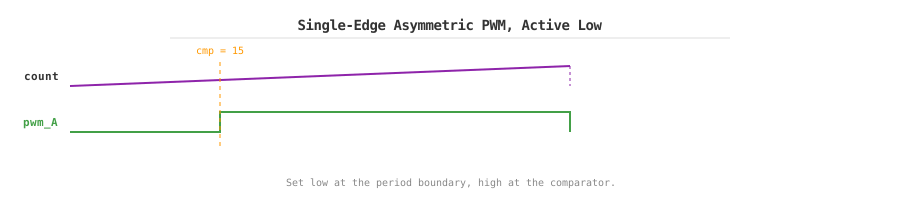
Up-counting, active-low PWM. Change the actions, rather than the wiring, when the output polarity is part of the design.
Place a pulse inside the period
When a short pulse must sit at a controlled position inside the cycle — an ADC sample window, a peripheral trigger pulse, or a latch strobe — two compare values choose its opening and closing edges:
ESP_ERROR_CHECK(mcpwm_generator_set_action_on_compare_event(
    generator, MCPWM_GEN_COMPARE_EVENT_ACTION(
        MCPWM_TIMER_DIRECTION_UP, comparator_a, MCPWM_GEN_ACTION_HIGH)));
ESP_ERROR_CHECK(mcpwm_generator_set_action_on_compare_event(
    generator, MCPWM_GEN_COMPARE_EVENT_ACTION(
        MCPWM_TIMER_DIRECTION_UP, comparator_b, MCPWM_GEN_ACTION_LOW)));
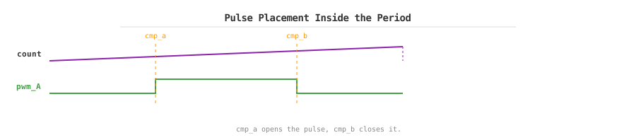
Pulse placement: the distance between the two compare values is the pulse width.
Set comparator_a below comparator_b. Moving both by the same tick offset changes the position without changing width; moving only one changes width. Hardware places both edges, so this is more precise than a timer callback.
Two-edge asymmetric PWM
When several edges must be placed independently within one cycle and the active interval does not need to stay symmetric around the center — for example in certain asymmetric inverter modulation or custom gate-drive timing — use two generators and two comparators. Each generator has its own edge per cycle, so the high time splits across the period boundary:
ESP_ERROR_CHECK(mcpwm_generator_set_action_on_compare_event(
    gen_a, MCPWM_GEN_COMPARE_EVENT_ACTION(
        MCPWM_TIMER_DIRECTION_UP, cmp_a, MCPWM_GEN_ACTION_HIGH)));
ESP_ERROR_CHECK(mcpwm_generator_set_action_on_compare_event(
    gen_a, MCPWM_GEN_COMPARE_EVENT_ACTION(
        MCPWM_TIMER_DIRECTION_UP, cmp_b, MCPWM_GEN_ACTION_LOW)));
ESP_ERROR_CHECK(mcpwm_generator_set_action_on_compare_event(
    gen_b, MCPWM_GEN_COMPARE_EVENT_ACTION(
        MCPWM_TIMER_DIRECTION_UP, cmp_a, MCPWM_GEN_ACTION_LOW)));
ESP_ERROR_CHECK(mcpwm_generator_set_action_on_compare_event(
    gen_b, MCPWM_GEN_COMPARE_EVENT_ACTION(
        MCPWM_TIMER_DIRECTION_UP, cmp_b, MCPWM_GEN_ACTION_HIGH)));
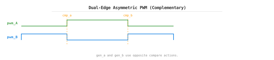
Dual-edge asymmetric (edge-aligned) PWM: two generators produce complementary outputs with two edges per cycle.
Center-aligned PWM
Motor drives, inverters, and power stages that care about harmonic behavior often prefer center-aligned PWM because it gives more symmetric switching and lower harmonic distortion. Select MCPWM_TIMER_COUNT_MODE_UP_DOWN when creating the timer, then use the same threshold in both directions:
ESP_ERROR_CHECK(mcpwm_generator_set_action_on_compare_event(
    generator, MCPWM_GEN_COMPARE_EVENT_ACTION(
        MCPWM_TIMER_DIRECTION_UP, comparator, MCPWM_GEN_ACTION_HIGH)));
ESP_ERROR_CHECK(mcpwm_generator_set_action_on_compare_event(
    generator, MCPWM_GEN_COMPARE_EVENT_ACTION(
        MCPWM_TIMER_DIRECTION_DOWN, comparator, MCPWM_GEN_ACTION_LOW)));
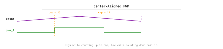
Center-aligned PWM: the up-count and down-count actions create matching edges around the period center.
The timer reaches its peak and returns to zero in each complete up-down cycle, so account for both legs when calculating frequency. Adding a second generator with opposite actions creates complementary logical outputs:
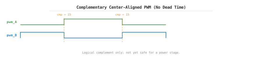
Complementary generator actions have no dead time by themselves; do not connect them directly to a power stage.
Warning
Logical complementary outputs are not yet safe half-bridge outputs. If the high-side and low-side devices have finite turn-off delay, add dead time and verify non-overlap at the actual gate pins.
Duty updates
Change duty by setting the comparator threshold, not the generator actions. The threshold is expressed in timer ticks: for an up-counting active-high waveform, compare_value / period_ticks is the duty ratio. Choose a timer resolution high enough that one tick gives the adjustment granularity the application needs.
mcpwm_comparator_set_compare_value(comparator, 25); // 50 %
Forced levels
Adjusting the comparator threshold changes the normal duty. When you instead need to temporarily take over the output, ignore all event actions, and hold a fixed level, use the force-level API. mcpwm_generator_set_force_level() takes a level and a hold_on flag:
level(second parameter) is the raw generator level to force:0or1overrides all event actions, while-1releases the force and returns control to event actions.hold_on(third parameter) decides how long the forced level lasts:trueholds it until another call releases it, whereasfalselets the next event action override it.
For example, mcpwm_generator_set_force_level(generator, 0, true) overrides all event actions and holds the raw generator low. Force acts before dead time and GPIO inversion, so confirm the physical pin level with a scope when using those features.
Force level is useful for power-up checks, a temporary post-fault safe output, or a mode-transition state. It is not a long-term replacement for a proper PWM configuration.
For a half bridge, add a second generator and configure the dead-time module to produce non-overlapping complementary outputs.
Dead time and half-bridge drive
Dead time delays an output edge, leaving a short interval in which both switches in a half bridge are off. It compensates for transistor turn-off delay and helps prevent shoot-through. Configure and verify it before connecting a power stage.
A half bridge drives a load from a DC bus through a high-side and a low-side switch. Both switches are usually N-channel MOSFETs: the low-side source sits at ground and is easy to drive, while the high-side source swings with the output, so its gate needs a drive voltage above the bus voltage. The MCPWM outputs are 3.3 V logic and cannot drive the gates directly. For example, an IRS2101 uses a separate low-voltage driver supply (VCC, typically 10-20 V), with COM connected to power ground. Its bootstrap diode should be connected from VCC to VB, and the external bootstrap capacitor between VB and VS; VS must be connected to the OUT switch node. The high-side output is HO and the low-side output is LO, and both drive their MOSFET gates through gate resistors. VCC is not the high-voltage DC bus: the bootstrap diode charges the bootstrap capacitor from the regulated driver supply while the low-side switch is on. If the two switches were turned on and off simultaneously, the switch that is still turning off would overlap the one already turning on, shorting the bus to ground through both switches. Dead time inserts a both-off gap so the next switch turns on only after the previous one has fully turned off:
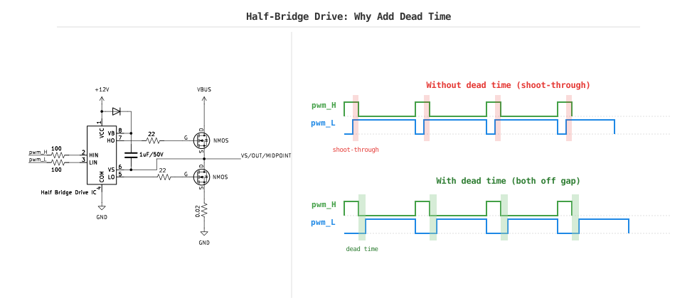
Half-bridge gate-driver circuit with bootstrap supply and dead-time comparison.
Create complementary outputs
Create two generators in one operator. Feed generator A into its own output with a rising-edge delay, then feed it into generator B with a falling-edge delay and inversion.
Note
Generator A is the first generator allocated from the operator handle, and generator B is the second.
mcpwm_dead_time_config_t dead_time = { .posedge_delay_ticks = 2 };
ESP_ERROR_CHECK(mcpwm_generator_set_dead_time(gen_a, gen_a, &dead_time));
dead_time = (mcpwm_dead_time_config_t) {
    .negedge_delay_ticks = 2,
    .flags.invert_output = true,
};
ESP_ERROR_CHECK(mcpwm_generator_set_dead_time(gen_a, gen_b, &dead_time));
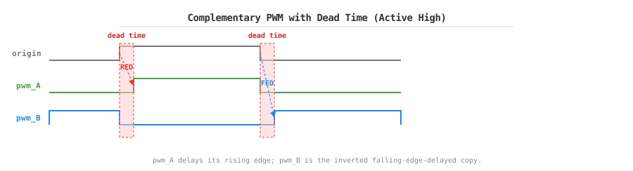
Complementary PWM with a dead-time interval between the switch transitions.
Understanding the routing and parameters
mcpwm_generator_set_dead_time(in_generator, out_generator, config) treats dead time as a small signal-processing stage. Passing the same generator for both handles changes that output in place. Passing gen_a as input and gen_b as output derives B from A, which is how the complementary example shares one PWM source.
posedge_delay_ticks delays a rising edge and negedge_delay_ticks delays a falling edge. Ticks use the connected timer's resolution, so a 2-tick setting at 10 MHz is 200 ns. The diagram below shows the basic effect: the rising edge of pwm_A is delayed by RED (Rising Edge Delay) ticks, and the falling edge of pwm_B is delayed by FED (Falling Edge Delay) ticks. Start with the maximum turn-off delay from the switch and gate-driver data sheets plus margin; then measure at the transistor gates and reduce it only after confirming that process, temperature, and layout still leave enough margin. Set both delays to zero to bypass the dead-time stage. invert_output changes polarity after that stage.
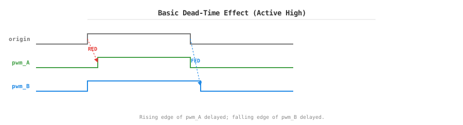
Basic dead-time effect: rising edge delayed (RED) and falling edge delayed (FED) relative to the original.
Important
Because of the topology of the rising-edge and falling-edge delay resources, it is recommended to call mcpwm_generator_set_dead_time() once for each generator to declare the intended routing. Even when only one generator needs a delay, call mcpwm_generator_set_dead_time() on the other generator with a zero-delay configuration to avoid unexpectedly affecting the other path, for example:
mcpwm_dead_time_config_t dead_time = { .negedge_delay_ticks = 2 };
ESP_ERROR_CHECK(mcpwm_generator_set_dead_time(gen_a, gen_a, &dead_time));
dead_time.negedge_delay_ticks = 0;
ESP_ERROR_CHECK(mcpwm_generator_set_dead_time(gen_b, gen_b, &dead_time));
Resource limits per operator
The hardware has one rising-edge and one falling-edge delay resource per operator, so do not assign the same delay type independently to both generators. The following requests the one rising-edge resource twice and is invalid:
mcpwm_dead_time_config_t rise_delay = { .posedge_delay_ticks = 10 };
ESP_ERROR_CHECK(mcpwm_generator_set_dead_time(gen_a, gen_a, &rise_delay));
// This second independent rising-edge delay cannot be allocated.
ESP_ERROR_CHECK(mcpwm_generator_set_dead_time(gen_b, gen_b, &rise_delay));
You may assign the rising delay to A and the falling delay to B. You may also use both delay resources for B while A bypasses the module. If the first generator uses both delay resources, the other generator cannot use dead time.
More output patterns
The complementary configuration above is the usual half-bridge starting point. Swap the output inversions to make both outputs active low while retaining the non-overlap:
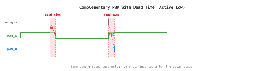
Active-low complementary outputs. The timing resources are the same; only the post-dead-time polarity changes.
Dead time is also useful when only one channel needs an edge delay. Pass a zero-delay configuration to one output to bypass it, then apply the available delay to the other output:
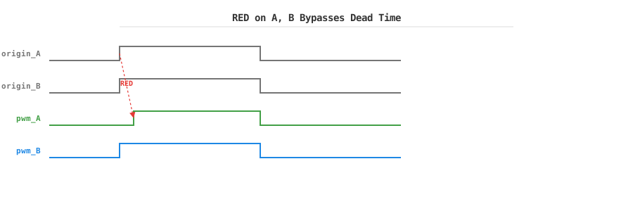
Delay A's rising edge while B bypasses dead time. This is not a complementary half bridge; it is an independent edge-placement tool.
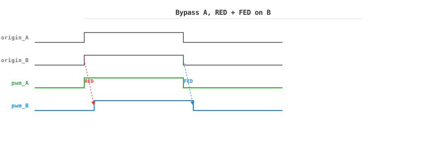
Bypass A and delay both edges of B, consuming both delay resources.
A single-edge delay can also be applied individually. The next diagram shows the falling edge delayed on B while A is bypassed, using only the FED resource:
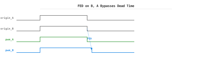
Apply only the falling-edge delay to B, leaving A unchanged. This uses one delay resource.
When the output is inverted, the dead-time behavior shifts accordingly. The following shows the active-low version of the basic delay, where the invert flag flips the polarity of both outputs:
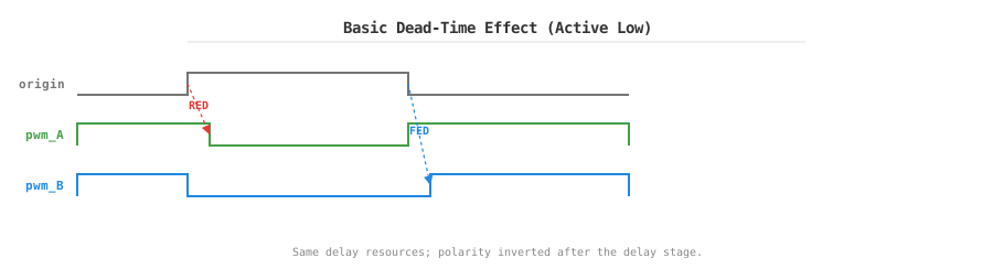
Active-low dead time: same delay resources, but the output polarity is inverted after the delay stage.
Note
For a waveform where each edge must have an independently movable position, use two comparators and generator actions instead. The dead-time module is the better choice when the requirement is specifically a delayed edge plus polarity control.
Update at a safe boundary
Set the operator's update_dead_time_on_tez, update_dead_time_on_tep, or update_dead_time_on_sync flag when a changed dead-time value must take effect only at a known boundary.
Note
Probe both physical gate pins: GPIO inversion, carrier modulation, and gate-driver polarity can all alter what appears at the transistor. When several stages invert the signal, two inversions can cancel out and look correct in software while the hardware does something unexpected, so always verify against the real waveform.
Other event sources
Generator actions can also react directly to GPIO fault events or a sync event:
mcpwm_generator_set_action_on_fault_event()— immediate hardware reaction to a GPIO fault. Uses limited operator trigger slots.mcpwm_generator_set_action_on_sync_event()— transition at a synchronization edge. Each generator has one sync-action slot.mcpwm_generator_set_action_on_brake_event()— per-generator output state during an operator brake. It is set per brake mode and timer direction; see Fault connection for a full example.
For safety policy and persistent braking, prefer the operator brake mechanism. A generator fault action is best for a local edge-level response; a brake defines the safe state and recovery behavior for the whole output stage.
API Reference
MCPWM Generator Driver Functions
Header File
This header file can be included with:
#include "driver/mcpwm_gen.h"
This header file is a part of the API provided by the
esp_driver_mcpwmcomponent. To declare that your component depends onesp_driver_mcpwm, add the following to your CMakeLists.txt:REQUIRES esp_driver_mcpwm
or
PRIV_REQUIRES esp_driver_mcpwm
Functions
-
esp_err_t mcpwm_new_generator(mcpwm_oper_handle_t oper, const mcpwm_generator_config_t *config, mcpwm_gen_handle_t *ret_gen)
Allocate MCPWM generator from given operator.
- Parameters:
oper -- [in] MCPWM operator, allocated by
mcpwm_new_operator()config -- [in] MCPWM generator configuration
ret_gen -- [out] Returned MCPWM generator
- Returns:
ESP_OK: Create MCPWM generator successfully
ESP_ERR_INVALID_ARG: Create MCPWM generator failed because of invalid argument
ESP_ERR_NO_MEM: Create MCPWM generator failed because out of memory
ESP_ERR_NOT_FOUND: Create MCPWM generator failed because can't find free resource
ESP_FAIL: Create MCPWM generator failed because of other error
-
esp_err_t mcpwm_del_generator(mcpwm_gen_handle_t gen)
Delete MCPWM generator.
- Parameters:
gen -- [in] MCPWM generator handle, allocated by
mcpwm_new_generator()- Returns:
ESP_OK: Delete MCPWM generator successfully
ESP_ERR_INVALID_ARG: Delete MCPWM generator failed because of invalid argument
ESP_FAIL: Delete MCPWM generator failed because of other error
-
esp_err_t mcpwm_generator_set_force_level(mcpwm_gen_handle_t gen, int level, bool hold_on)
Set force level for MCPWM generator.
Note
The force level will be applied to the generator immediately, regardless any other events that would change the generator's behaviour.
Note
If the
hold_onis true, the force level will retain forever, until user removes the force level by setting the force level to-1.Note
If the
hold_onis false, the force level can be overridden by the next event action.Note
The force level set by this function can be inverted by GPIO matrix or dead-time module. So the level set here doesn't equal to the final output level.
- Parameters:
gen -- [in] MCPWM generator handle, allocated by
mcpwm_new_generator()level -- [in] GPIO level to be applied to MCPWM generator, specially, -1 means to remove the force level
hold_on -- [in] Whether the forced PWM level should retain (i.e. will remain unchanged until manually remove the force level)
- Returns:
ESP_OK: Set force level for MCPWM generator successfully
ESP_ERR_INVALID_ARG: Set force level for MCPWM generator failed because of invalid argument
ESP_FAIL: Set force level for MCPWM generator failed because of other error
-
esp_err_t mcpwm_generator_set_action_on_timer_event(mcpwm_gen_handle_t gen, mcpwm_gen_timer_event_action_t ev_act)
Set generator action on MCPWM timer event.
- Parameters:
gen -- [in] MCPWM generator handle, allocated by
mcpwm_new_generator()ev_act -- [in] MCPWM timer event action, can be constructed by
MCPWM_GEN_TIMER_EVENT_ACTIONhelper macro
- Returns:
ESP_OK: Set generator action successfully
ESP_ERR_INVALID_ARG: Set generator action failed because of invalid argument
ESP_ERR_INVALID_STATE: Set generator action failed because of timer is not connected to operator
ESP_FAIL: Set generator action failed because of other error
-
esp_err_t mcpwm_generator_set_action_on_compare_event(mcpwm_gen_handle_t generator, mcpwm_gen_compare_event_action_t ev_act)
Set generator action on MCPWM compare event.
- Parameters:
generator -- [in] MCPWM generator handle, allocated by
mcpwm_new_generator()ev_act -- [in] MCPWM compare event action, can be constructed by
MCPWM_GEN_COMPARE_EVENT_ACTIONhelper macro
- Returns:
ESP_OK: Set generator action successfully
ESP_ERR_INVALID_ARG: Set generator action failed because of invalid argument
ESP_FAIL: Set generator action failed because of other error
-
esp_err_t mcpwm_generator_set_action_on_brake_event(mcpwm_gen_handle_t generator, mcpwm_gen_brake_event_action_t ev_act)
Set generator action on MCPWM brake event.
- Parameters:
generator -- [in] MCPWM generator handle, allocated by
mcpwm_new_generator()ev_act -- [in] MCPWM brake event action, can be constructed by
MCPWM_GEN_BRAKE_EVENT_ACTIONhelper macro
- Returns:
ESP_OK: Set generator action successfully
ESP_ERR_INVALID_ARG: Set generator action failed because of invalid argument
ESP_FAIL: Set generator action failed because of other error
-
esp_err_t mcpwm_generator_set_action_on_fault_event(mcpwm_gen_handle_t generator, mcpwm_gen_fault_event_action_t ev_act)
Set generator action on MCPWM Fault event.
- Parameters:
generator -- [in] MCPWM generator handle, allocated by
mcpwm_new_generator()ev_act -- [in] MCPWM trigger event action, can be constructed by
MCPWM_GEN_FAULT_EVENT_ACTIONhelper macro
- Returns:
ESP_OK: Set generator action successfully
ESP_ERR_INVALID_ARG: Set generator action failed because of invalid argument
ESP_FAIL: Set generator action failed because of other error
-
esp_err_t mcpwm_generator_set_action_on_sync_event(mcpwm_gen_handle_t generator, mcpwm_gen_sync_event_action_t ev_act)
Set generator action on MCPWM Sync event.
Note
The trigger only support one sync action, regardless of the kinds. Should not call this function more than once.
- Parameters:
generator -- [in] MCPWM generator handle, allocated by
mcpwm_new_generator()ev_act -- [in] MCPWM trigger event action, can be constructed by
MCPWM_GEN_SYNC_EVENT_ACTIONhelper macro
- Returns:
ESP_OK: Set generator action successfully
ESP_ERR_INVALID_ARG: Set generator action failed because of invalid argument
ESP_FAIL: Set generator action failed because of other error
-
esp_err_t mcpwm_generator_set_dead_time(mcpwm_gen_handle_t in_generator, mcpwm_gen_handle_t out_generator, const mcpwm_dead_time_config_t *config)
Set dead time for MCPWM generator.
Note
Due to a hardware limitation, you can't set rising edge delay for both MCPWM generator 0 and 1 at the same time, otherwise, there will be a conflict inside the dead time module. The same goes for the falling edge setting. But you can set both the rising edge and falling edge delay for the same MCPWM generator.
- Parameters:
in_generator -- [in] MCPWM generator, before adding the dead time
out_generator -- [in] MCPWM generator, after adding the dead time
config -- [in] MCPWM dead time configuration
- Returns:
ESP_OK: Set dead time for MCPWM generator successfully
ESP_ERR_INVALID_ARG: Set dead time for MCPWM generator failed because of invalid argument
ESP_ERR_INVALID_STATE: Set dead time for MCPWM generator failed because of invalid state (e.g. delay module is already in use by other generator)
ESP_FAIL: Set dead time for MCPWM generator failed because of other error
Structures
-
struct mcpwm_generator_config_t
MCPWM generator configuration.
Public Members
-
int gen_gpio_num
The GPIO number used to output the PWM signal
-
struct mcpwm_generator_config_t::extra_mcpwm_generator_flags flags
Extra configuration flags for generator
-
int gen_gpio_num
-
struct mcpwm_gen_timer_event_action_t
Generator action on specific timer event.
Public Members
-
mcpwm_timer_direction_t direction
Timer direction
-
mcpwm_timer_event_t event
Timer event
-
mcpwm_generator_action_t action
Generator action should perform
-
mcpwm_timer_direction_t direction
-
struct mcpwm_gen_compare_event_action_t
Generator action on specific comparator event.
Public Members
-
mcpwm_timer_direction_t direction
Timer direction
-
mcpwm_cmpr_handle_t comparator
Comparator handle
-
mcpwm_generator_action_t action
Generator action should perform
-
mcpwm_timer_direction_t direction
-
struct mcpwm_gen_brake_event_action_t
Generator action on specific brake event.
Public Members
-
mcpwm_timer_direction_t direction
Timer direction
-
mcpwm_operator_brake_mode_t brake_mode
Brake mode
-
mcpwm_generator_action_t action
Generator action should perform
-
mcpwm_timer_direction_t direction
-
struct mcpwm_gen_fault_event_action_t
Generator action on specific fault event.
Public Members
-
mcpwm_timer_direction_t direction
Timer direction
-
mcpwm_fault_handle_t fault
Which fault as the trigger. Only support GPIO fault
-
mcpwm_generator_action_t action
Generator action should perform
-
mcpwm_timer_direction_t direction
-
struct mcpwm_gen_sync_event_action_t
Generator action on specific sync event.
Public Members
-
mcpwm_timer_direction_t direction
Timer direction
-
mcpwm_sync_handle_t sync
Which sync as the trigger
-
mcpwm_generator_action_t action
Generator action should perform
-
mcpwm_timer_direction_t direction
-
struct mcpwm_dead_time_config_t
MCPWM dead time configuration structure.
Public Members
-
uint32_t posedge_delay_ticks
delay time applied to rising edge, 0 means no rising delay time
-
uint32_t negedge_delay_ticks
delay time applied to falling edge, 0 means no falling delay time
-
uint32_t invert_output
Invert the signal after applied the dead time
-
struct mcpwm_dead_time_config_t flags
Extra flags for dead time configuration
-
uint32_t posedge_delay_ticks
Macros
-
MCPWM_GEN_TIMER_EVENT_ACTION(dir, ev, act)
Help macros to construct a mcpwm_gen_timer_event_action_t entry.
-
MCPWM_GEN_COMPARE_EVENT_ACTION(dir, cmp, act)
Help macros to construct a mcpwm_gen_compare_event_action_t entry.
-
MCPWM_GEN_BRAKE_EVENT_ACTION(dir, mode, act)
Help macros to construct a mcpwm_gen_brake_event_action_t entry.
-
MCPWM_GEN_FAULT_EVENT_ACTION(dir, flt, act)
Help macros to construct a mcpwm_gen_fault_event_action_t entry.
-
MCPWM_GEN_SYNC_EVENT_ACTION(dir, syn, act)
Help macros to construct a mcpwm_gen_sync_event_action_t entry.