MCPWM Timer: Set the Frequency
The timer is the time base for every PWM output attached to its operator. It counts ticks at resolution_hz and wraps around at period_ticks. Choose the resolution first — it determines the finest step of edge placement — then choose the period for the target frequency.
For a servo, speed loop, or inverter, the timer answers the two most basic questions: how fine is one tick, and how long is one PWM cycle. Comparators and generators only place edges on top of that time base.
Build a 20 kHz time base
For an up-counting timer, period_ticks = resolution_hz / frequency_hz. The following timer has a 1 MHz tick (one microsecond per tick) and a 50-tick period, giving 20 kHz. The diagram below shows the counter climbing from 0 to 50, then resetting — the TEZ (timer event zero) and TEP (timer event peak) markers are the two boundaries that generators use.
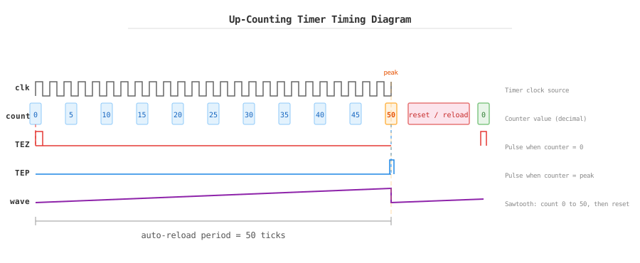
Up-counting timer: the counter forms a sawtooth, rising from 0 to 50, firing TEZ at zero and TEP at peak.
mcpwm_timer_handle_t timer = NULL;
mcpwm_timer_config_t timer_config = {
    .group_id = 0,
    .clk_src = MCPWM_TIMER_CLK_SRC_DEFAULT,
    .resolution_hz = 1000000,
    .period_ticks = 50,
    .count_mode = MCPWM_TIMER_COUNT_MODE_UP,
};
ESP_ERROR_CHECK(mcpwm_new_timer(&timer_config, &timer));
The timer configuration is worth reading field by field, because a few important knobs are not shown in the example:
group_id— the MCPWM group the timer is allocated from. Chips may expose more than one groups; each group bundles timers, operators, comparators, and generators that share clock dividers.0selects the first group, which is enough for most designs.clk_src— the clock that feeds the timer.MCPWM_TIMER_CLK_SRC_DEFAULTselects a PLL clock and is right for almost every application. On targets with extra sources, you can pick one explicitly — for example to keep the timer counting when the PLL is switched off, such as during light sleep.resolution_hz— the tick rate of the counter. One tick lasts1 / resolution_hzseconds, so 1 MHz means one microsecond per tick. This sets the finest edge step available to the comparator.period_ticks— the length of one full PWM cycle in ticks. The frequency isresolution_hz / period_ticks.count_mode— whether the counter counts up only (edge-aligned PWM) or up and down (center-aligned PWM). See Counting modes and waveforms for the two shapes; the hardware also supports counting down.intr_priority— the interrupt priority used by the timer callbacks. Not setting it (0) lets the driver choose a low priority; raise it when a callback must preempt other ISRs, for example in tightly timed motor control.
The example does not touch flags, so all of them are off — which is the safe default. Two of them are worth knowing:
update_period_on_emptyandupdate_period_on_sync— off by default, somcpwm_timer_set_period()takes effect immediately. Turn them on to defer frequency changes to a safe boundary; see Safe frequency updates.allow_pd— lets the MCPWM power domain switch off during sleep. The driver then backs up and restores the timer registers around the sleep transition, saving power at the cost of extra RAM.
Do not start the timer yet. First create and connect the operator, comparator, and generator (see the following pages), then enable and start:
ESP_ERROR_CHECK(mcpwm_timer_enable(timer));
ESP_ERROR_CHECK(mcpwm_timer_start_stop(timer, MCPWM_TIMER_START_NO_STOP));
mcpwm_timer_enable() activates the services the timer needs to run: it enables the timer interrupt and, with power management on, holds the group's power-management lock so clock scaling cannot disturb PWM timing. mcpwm_timer_start_stop() then starts and later stops the counter. Call mcpwm_timer_disable() to reverse the enable before freeing the timer with mcpwm_del_timer().
The third argument of mcpwm_timer_start_stop() selects the stop behavior:
MCPWM_TIMER_START_NO_STOP— runs continuously until you explicitly stop it.MCPWM_TIMER_START_STOP_EMPTY— stops automatically when the next count reaches zero (TEZ). Use this for a single-shot or synchronized start where the cycle should complete before stopping.MCPWM_TIMER_START_STOP_FULL— stops automatically when the next count reaches the peak (TEP). Use this for a single cycle that ends at the period boundary.
Counting modes and waveforms
In up mode, the counter counts from 0 to period_ticks and resets. The waveform is a sawtooth and the PWM edges align to one side of the period — this is called edge-aligned PWM.
In up-down mode, the counter counts up to period_ticks / 2 and then down to 0. The waveform is a triangle and the PWM edges are centered around the middle of the period — center-aligned PWM. Center-aligned PWM is preferred for motor control because it produces less harmonic distortion.
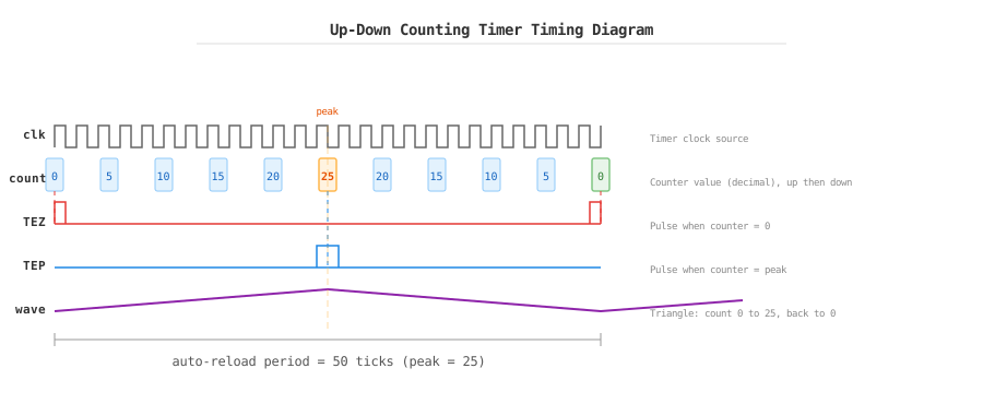
Up-down counting: the counter forms a triangle, rising to 25 (half of 50), then falling back to 0.
The frequency is still resolution_hz / period_ticks in both modes. Choose a resolution high enough for the duty precision you need, then choose a period for the desired frequency.
Important
period_ticks is the total number of ticks in one full PWM cycle. It is not always the same thing as the timer peak value.
In
MCPWM_TIMER_COUNT_MODE_UP, the counter runs0 -> period_ticks.In
MCPWM_TIMER_COUNT_MODE_UP_DOWN, the hardware peak isperiod_ticks / 2, and the full cycle is0 -> peak -> 0.
For example, with resolution_hz = 1 MHz and period_ticks = 50: up mode counts 0 -> 50, while up-down mode counts 0 -> 25 -> 0. Both still take 50 microseconds for a full cycle, so both are 20 kHz. What changes is the edge placement, not the period length.
Safe frequency updates
mcpwm_timer_set_period() takes effect immediately by default. That can truncate the current cycle and produce a runt pulse. Set update_period_on_empty to defer the new period until the counter reaches zero, or update_period_on_sync to defer it until a sync event. When changing the period, also scale the comparator threshold if the duty ratio must remain unchanged:
// Keep 40 % duty while changing a 50-tick period to 100 ticks.
ESP_ERROR_CHECK(mcpwm_comparator_set_compare_value(comparator, 40));
ESP_ERROR_CHECK(mcpwm_timer_set_period(timer, 100));
In most runtime tuning paths, change the comparator to change duty and touch the timer only when the PWM frequency itself must change. Motor-control and power-conversion applications should usually combine this with update_period_on_empty or a sync-triggered update to avoid mid-cycle changes.
Timer event callbacks
The timer can notify your application at peak (on_full), zero (on_empty), or when it stops (on_stop). Register callbacks before enabling the timer. They run in ISR context: do not block, allocate memory, or call normal FreeRTOS APIs; use ...FromISR variants when needed.
Note
The timer and capture timer may share a divider with other objects in the same group. When one group needs several resolutions, create objects in monotonic requested-resolution order to avoid divider conflicts. See advanced topics for the full rule.
static bool IRAM_ATTR on_timer_empty(mcpwm_timer_handle_t timer,
                                     const mcpwm_timer_event_data_t *edata,
                                     void *user_ctx)
{
    BaseType_t high_task_woken = pdFALSE;
    vTaskNotifyGiveFromISR((TaskHandle_t)user_ctx, &high_task_woken);
    return high_task_woken == pdTRUE;
}

mcpwm_timer_event_callbacks_t cbs = { .on_empty = on_timer_empty };
ESP_ERROR_CHECK(mcpwm_timer_register_event_callbacks(timer, &cbs,
                                                      xTaskGetCurrentTaskHandle()));
The synchronization page shows how a timer can reset to a chosen phase on a sync edge.
API Reference
MCPWM Timer Driver Functions
Header File
This header file can be included with:
#include "driver/mcpwm_timer.h"
This header file is a part of the API provided by the
esp_driver_mcpwmcomponent. To declare that your component depends onesp_driver_mcpwm, add the following to your CMakeLists.txt:REQUIRES esp_driver_mcpwm
or
PRIV_REQUIRES esp_driver_mcpwm
Functions
-
esp_err_t mcpwm_new_timer(const mcpwm_timer_config_t *config, mcpwm_timer_handle_t *ret_timer)
Create MCPWM timer.
- Parameters:
config -- [in] MCPWM timer configuration
ret_timer -- [out] Returned MCPWM timer handle
- Returns:
ESP_OK: Create MCPWM timer successfully
ESP_ERR_INVALID_ARG: Create MCPWM timer failed because of invalid argument
ESP_ERR_NO_MEM: Create MCPWM timer failed because out of memory
ESP_ERR_NOT_FOUND: Create MCPWM timer failed because all hardware timers are used up and no more free one
ESP_FAIL: Create MCPWM timer failed because of other error
-
esp_err_t mcpwm_timer_get_resolution(mcpwm_timer_handle_t timer, uint32_t *out_resolution)
Get MCPWM timer resolution, in Hz.
- Parameters:
timer -- [in] MCPWM timer handle, allocated by
mcpwm_new_timer()out_resolution -- [out] Returned timer resolution, in Hz
- Returns:
ESP_OK: Get timer resolution successfully
ESP_ERR_INVALID_ARG: Get timer resolution failed because of invalid argument
-
esp_err_t mcpwm_del_timer(mcpwm_timer_handle_t timer)
Delete MCPWM timer.
- Parameters:
timer -- [in] MCPWM timer handle, allocated by
mcpwm_new_timer()- Returns:
ESP_OK: Delete MCPWM timer successfully
ESP_ERR_INVALID_ARG: Delete MCPWM timer failed because of invalid argument
ESP_ERR_INVALID_STATE: Delete MCPWM timer failed because timer is not in init state
ESP_FAIL: Delete MCPWM timer failed because of other error
-
esp_err_t mcpwm_timer_set_period(mcpwm_timer_handle_t timer, uint32_t period_ticks)
Set a new period for MCPWM timer.
Note
If
mcpwm_timer_config_t::update_period_on_emptyandmcpwm_timer_config_t::update_period_on_syncare not set, the new period will take effect immediately. Otherwise, the new period will take effect when timer counts to zero or on sync event.Note
You may need to use
mcpwm_comparator_set_compare_valueto set a new compare value for MCPWM comparator in order to keep the same PWM duty cycle.- Parameters:
timer -- [in] MCPWM timer handle, allocated by
mcpwm_new_timerperiod_ticks -- [in] New period in count ticks
- Returns:
ESP_OK: Set new period for MCPWM timer successfully
ESP_ERR_INVALID_ARG: Set new period for MCPWM timer failed because of invalid argument
ESP_FAIL: Set new period for MCPWM timer failed because of other error
-
esp_err_t mcpwm_timer_enable(mcpwm_timer_handle_t timer)
Enable MCPWM timer.
- Parameters:
timer -- [in] MCPWM timer handle, allocated by
mcpwm_new_timer()- Returns:
ESP_OK: Enable MCPWM timer successfully
ESP_ERR_INVALID_ARG: Enable MCPWM timer failed because of invalid argument
ESP_ERR_INVALID_STATE: Enable MCPWM timer failed because timer is enabled already
ESP_FAIL: Enable MCPWM timer failed because of other error
-
esp_err_t mcpwm_timer_disable(mcpwm_timer_handle_t timer)
Disable MCPWM timer.
- Parameters:
timer -- [in] MCPWM timer handle, allocated by
mcpwm_new_timer()- Returns:
ESP_OK: Disable MCPWM timer successfully
ESP_ERR_INVALID_ARG: Disable MCPWM timer failed because of invalid argument
ESP_ERR_INVALID_STATE: Disable MCPWM timer failed because timer is disabled already
ESP_FAIL: Disable MCPWM timer failed because of other error
-
esp_err_t mcpwm_timer_start_stop(mcpwm_timer_handle_t timer, mcpwm_timer_start_stop_cmd_t command)
Send specific start/stop commands to MCPWM timer.
- Parameters:
timer -- [in] MCPWM timer handle, allocated by
mcpwm_new_timer()command -- [in] Supported command list for MCPWM timer
- Returns:
ESP_OK: Start or stop MCPWM timer successfully
ESP_ERR_INVALID_ARG: Start or stop MCPWM timer failed because of invalid argument
ESP_ERR_INVALID_STATE: Start or stop MCPWM timer failed because timer is not enabled
ESP_FAIL: Start or stop MCPWM timer failed because of other error
-
esp_err_t mcpwm_timer_register_event_callbacks(mcpwm_timer_handle_t timer, const mcpwm_timer_event_callbacks_t *cbs, void *user_data)
Set event callbacks for MCPWM timer.
Note
The first call to this function needs to be before the call to
mcpwm_timer_enableNote
User can deregister a previously registered callback by calling this function and setting the callback member in the
cbsstructure to NULL.- Parameters:
timer -- [in] MCPWM timer handle, allocated by
mcpwm_new_timer()cbs -- [in] Group of callback functions
user_data -- [in] User data, which will be passed to callback functions directly
- Returns:
ESP_OK: Set event callbacks successfully
ESP_ERR_INVALID_ARG: Set event callbacks failed because of invalid argument
ESP_ERR_INVALID_STATE: Set event callbacks failed because timer is not in init state
ESP_FAIL: Set event callbacks failed because of other error
-
esp_err_t mcpwm_timer_set_phase_on_sync(mcpwm_timer_handle_t timer, const mcpwm_timer_sync_phase_config_t *config)
Set sync phase for MCPWM timer.
- Parameters:
timer -- [in] MCPWM timer handle, allocated by
mcpwm_new_timer()config -- [in] MCPWM timer sync phase configuration
- Returns:
ESP_OK: Set sync phase for MCPWM timer successfully
ESP_ERR_INVALID_ARG: Set sync phase for MCPWM timer failed because of invalid argument
ESP_FAIL: Set sync phase for MCPWM timer failed because of other error
Structures
-
struct mcpwm_timer_event_callbacks_t
Group of supported MCPWM timer event callbacks.
Note
The callbacks are all running under ISR environment
Public Members
-
mcpwm_timer_event_cb_t on_full
callback function when MCPWM timer counts to peak value
-
mcpwm_timer_event_cb_t on_empty
callback function when MCPWM timer counts to zero
-
mcpwm_timer_event_cb_t on_stop
callback function when MCPWM timer stops
-
mcpwm_timer_event_cb_t on_full
-
struct mcpwm_timer_config_t
MCPWM timer configuration.
Public Members
-
int group_id
Specify from which group to allocate the MCPWM timer
-
mcpwm_timer_clock_source_t clk_src
MCPWM timer clock source
-
uint32_t resolution_hz
Counter resolution in Hz The step size of each count tick equals to (1 / resolution_hz) seconds
-
mcpwm_timer_count_mode_t count_mode
Count mode
-
uint32_t period_ticks
Number of count ticks within a period. For up-down mode, the timer peak value is half of the period_ticks
-
int intr_priority
MCPWM timer interrupt priority, if set to 0, the driver will try to allocate an interrupt with a relative low priority (1,2,3)
-
struct mcpwm_timer_config_t::extra_mcpwm_timer_flags flags
Extra configuration flags for timer
-
struct extra_mcpwm_timer_flags
Extra configuration flags for MCPWM timer.
Public Members
-
uint32_t update_period_on_empty
Whether to update period when timer counts to zero
-
uint32_t update_period_on_sync
Whether to update period on sync event
-
uint32_t allow_pd
Set to allow power down. When this flag set, the driver will backup/restore the MCPWM registers before/after entering/exist sleep mode. By this approach, the system can power off MCPWM's power domain. This can save power, but at the expense of more RAM being consumed.
-
uint32_t update_period_on_empty
-
int group_id
-
struct mcpwm_timer_sync_phase_config_t
MCPWM Timer sync phase configuration.
Public Members
-
mcpwm_sync_handle_t sync_src
The sync event source. Set to NULL will disable the timer being synced by others
-
uint32_t count_value
The count value that should lock to upon sync event
-
mcpwm_timer_direction_t direction
The count direction that should lock to upon sync event
-
mcpwm_sync_handle_t sync_src