MCPWM Synchronization: Align PWM Phases
Why sync is needed
Each MCPWM timer is an independent hardware counter. When you call mcpwm_timer_start() on two timers, the two writes are issued sequentially by the CPU — the second timer starts a few dozen CPU cycles after the first. Even if both are configured with the same period, their counters will be at different positions relative to the cycle, and the phase relationship between their PWM outputs is unpredictable.
Synchronization solves this by loading a chosen count and direction into a running timer when a sync edge arrives. The timers must already be running; sync does not start or stop them. It is a runtime phase correction mechanism.
If the sync edge arrives every period (for example, from a timer sync source at TEZ), the correction repeats each cycle, keeping the phase locked indefinitely. This is the typical use case: one timer acts as the reference, and other timers re-align to it on every period.
MCPWM provides three types of sync sources. All sources produce a handle of type mcpwm_sync_handle_t, and any source can feed any timer in the same group.
GPIO sync source
A GPIO sync source reacts to an edge on an external pin — useful when an external controller, sensor, or encoder provides a periodic reference.
mcpwm_sync_handle_t sync = NULL;
ESP_ERROR_CHECK(mcpwm_new_gpio_sync_src(
    &(mcpwm_gpio_sync_src_config_t) {
        .group_id = 0,
        .gpio_num = 5,
        .flags.active_neg = false,
    }, &sync));
The GPIO sync source configuration is small:
Software sync source
A software sync source produces a sync edge on demand from application code. It has no configuration fields; create it and activate it when needed.
mcpwm_sync_handle_t soft_sync = NULL;
ESP_ERROR_CHECK(mcpwm_new_soft_sync_src(NULL, &soft_sync));

// later, when the application decides to synchronize:
ESP_ERROR_CHECK(mcpwm_soft_sync_activate(soft_sync));
Note
Activate the soft sync only after binding it to a timer via mcpwm_timer_set_phase_on_sync() or mcpwm_capture_timer_set_phase_on_sync(). The driver does not assign a timer at creation time; calling mcpwm_soft_sync_activate() before binding is undefined behavior.
This is useful when timers are already running and the application needs to trigger a one-time phase correction — for example, after recovering from a fault, or before starting a new control cycle. Because the sync is one-shot, the phase relationship will drift over time if no further sync edges arrive. For sustained phase lock, use a periodic source (GPIO or timer sync).
Timer sync source
A timer sync source emits a sync edge when the timer reaches a chosen event — for example, every time the timer hits zero (TEZ). This lets one timer act as a periodic reference for other timers, keeping their phase locked every cycle.
mcpwm_sync_handle_t timer_sync = NULL;
ESP_ERROR_CHECK(mcpwm_new_timer_sync_src(
    timer_a,
    &(mcpwm_timer_sync_src_config_t) {
        .timer_event = MCPWM_TIMER_EVENT_EMPTY,
    },
    &timer_sync));
timer_event— the timer event that triggers the sync output. Common choices areMCPWM_TIMER_EVENT_EMPTY(zero) for the start of each period orMCPWM_TIMER_EVENT_PEAKfor the peak value. In up-counting mode the peak is the period boundary; in up-down mode the peak is the midpoint of the period.propagate_input_sync— when set, the timer forwards its own received input sync to its sync output, enabling a chain of timers without extra GPIO wiring. In this mode the hardware selects the input sync as the output source, so thetimer_eventfield is ignored.
A timer can create at most one sync source. Multiple timers can receive the same sync source.
Because the timer sync source fires every period, the receiving timer gets corrected on every cycle. This is the most common way to maintain a stable phase relationship between multiple PWM channels.
Set the receiving phase
No matter which source type you chose, the receiving timer uses the same API. Call mcpwm_timer_set_phase_on_sync() to configure what happens when the sync edge arrives. The timer must already be running for the sync to take effect.
ESP_ERROR_CHECK(mcpwm_timer_set_phase_on_sync(timer,
    &(mcpwm_timer_sync_phase_config_t) {
        .sync_src = sync,
        .count_value = 25,
        .direction = MCPWM_TIMER_DIRECTION_UP,
    }));
sync_src— the source object. Set it toNULLto detach synchronization.count_value— the count loaded when the sync event arrives. Keep it within the timer period.direction— the counting direction after loading.
Two outputs with a 90-degree phase shift
Now that you know all three source types and how to set the receiving phase, here is a complete example. It uses a timer sync source: timer_a emits a sync every time it reaches zero, and timer_b receives that sync and loads count_value = 25, producing a 90-degree phase lag. Because the sync repeats each period, the phase relationship between the two channels is maintained indefinitely.
mcpwm_timer_handle_t timer_a = NULL;
mcpwm_timer_handle_t timer_b = NULL;
mcpwm_sync_handle_t timer_a_sync = NULL;

// timer_a and timer_b already exist, both with period_ticks = 100

ESP_ERROR_CHECK(mcpwm_new_timer_sync_src(
    timer_a,
    &(mcpwm_timer_sync_src_config_t) {
        .timer_event = MCPWM_TIMER_EVENT_EMPTY,
    },
    &timer_a_sync));

ESP_ERROR_CHECK(mcpwm_timer_set_phase_on_sync(timer_b,
    &(mcpwm_timer_sync_phase_config_t) {
        .sync_src = timer_a_sync,
        .count_value = 25,
        .direction = MCPWM_TIMER_DIRECTION_UP,
    }));

// timer_a emits sync at TEZ; timer_b receives it and continues from tick 25.
Understand lead and lag
In the sketch below, PWM_A starts its cycle first and PWM_B appears one quarter cycle later. That means PWM_B lags PWM_A by 90 degrees; equivalently, PWM_A leads PWM_B by 90 degrees.
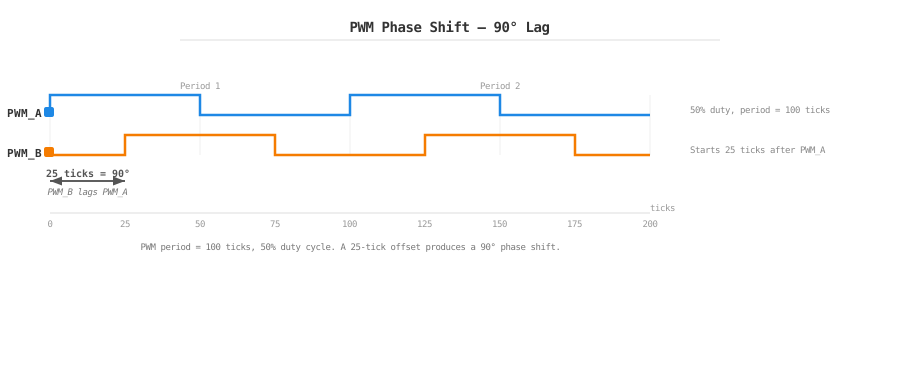
PWM_A and PWM_B with a 90-degree phase shift: PWM_B starts 25 ticks after PWM_A.
Other considerations
The capture timer can use the same source through mcpwm_capture_timer_set_phase_on_sync(); capture always counts up. The receiver and source must remain in the same group. Delete a source only after detaching or deleting every object that uses it.
API Reference
MCPWM Synchronization Driver Functions
Header File
This header file can be included with:
#include "driver/mcpwm_sync.h"
This header file is a part of the API provided by the
esp_driver_mcpwmcomponent. To declare that your component depends onesp_driver_mcpwm, add the following to your CMakeLists.txt:REQUIRES esp_driver_mcpwm
or
PRIV_REQUIRES esp_driver_mcpwm
Functions
-
esp_err_t mcpwm_new_timer_sync_src(mcpwm_timer_handle_t timer, const mcpwm_timer_sync_src_config_t *config, mcpwm_sync_handle_t *ret_sync)
Create MCPWM timer sync source.
- Parameters:
timer -- [in] MCPWM timer handle, allocated by
mcpwm_new_timer()config -- [in] MCPWM timer sync source configuration
ret_sync -- [out] Returned MCPWM sync handle
- Returns:
ESP_OK: Create MCPWM timer sync source successfully
ESP_ERR_INVALID_ARG: Create MCPWM timer sync source failed because of invalid argument
ESP_ERR_NO_MEM: Create MCPWM timer sync source failed because out of memory
ESP_ERR_INVALID_STATE: Create MCPWM timer sync source failed because the timer has created a sync source before
ESP_FAIL: Create MCPWM timer sync source failed because of other error
-
esp_err_t mcpwm_new_gpio_sync_src(const mcpwm_gpio_sync_src_config_t *config, mcpwm_sync_handle_t *ret_sync)
Create MCPWM GPIO sync source.
- Parameters:
config -- [in] MCPWM GPIO sync source configuration
ret_sync -- [out] Returned MCPWM GPIO sync handle
- Returns:
ESP_OK: Create MCPWM GPIO sync source successfully
ESP_ERR_INVALID_ARG: Create MCPWM GPIO sync source failed because of invalid argument
ESP_ERR_NO_MEM: Create MCPWM GPIO sync source failed because out of memory
ESP_ERR_NOT_FOUND: Create MCPWM GPIO sync source failed because can't find free resource
ESP_FAIL: Create MCPWM GPIO sync source failed because of other error
-
esp_err_t mcpwm_new_soft_sync_src(const mcpwm_soft_sync_config_t *config, mcpwm_sync_handle_t *ret_sync)
Create MCPWM software sync source.
- Parameters:
config -- [in] MCPWM software sync source configuration
ret_sync -- [out] Returned software sync handle
- Returns:
ESP_OK: Create MCPWM software sync successfully
ESP_ERR_INVALID_ARG: Create MCPWM software sync failed because of invalid argument
ESP_ERR_NO_MEM: Create MCPWM software sync failed because out of memory
ESP_FAIL: Create MCPWM software sync failed because of other error
-
esp_err_t mcpwm_del_sync_src(mcpwm_sync_handle_t sync)
Delete MCPWM sync source.
- Parameters:
sync -- [in] MCPWM sync handle, allocated by
mcpwm_new_timer_sync_src()ormcpwm_new_gpio_sync_src()ormcpwm_new_soft_sync_src()- Returns:
ESP_OK: Delete MCPWM sync source successfully
ESP_ERR_INVALID_ARG: Delete MCPWM sync source failed because of invalid argument
ESP_FAIL: Delete MCPWM sync source failed because of other error
-
esp_err_t mcpwm_soft_sync_activate(mcpwm_sync_handle_t sync)
Activate the software sync, trigger the sync event for once.
- Parameters:
sync -- [in] MCPWM soft sync handle, allocated by
mcpwm_new_soft_sync_src()- Returns:
ESP_OK: Trigger MCPWM software sync event successfully
ESP_ERR_INVALID_ARG: Trigger MCPWM software sync event failed because of invalid argument
ESP_FAIL: Trigger MCPWM software sync event failed because of other error
Structures
-
struct mcpwm_timer_sync_src_config_t
MCPWM timer sync source configuration.
Public Members
-
mcpwm_timer_event_t timer_event
Timer event, upon which MCPWM timer will generate the sync signal
-
struct mcpwm_timer_sync_src_config_t::extra_mcpwm_timer_sync_src_flags flags
Extra configuration flags for timer sync source
-
mcpwm_timer_event_t timer_event
-
struct mcpwm_gpio_sync_src_config_t
MCPWM GPIO sync source configuration.
Public Members
-
int group_id
MCPWM group ID
-
int gpio_num
GPIO used by sync source
-
struct mcpwm_gpio_sync_src_config_t::extra_mcpwm_gpio_sync_src_flags flags
Extra configuration flags for GPIO sync source
-
int group_id
-
struct mcpwm_soft_sync_config_t
MCPWM software sync configuration structure.