SPI LCD Introduction
Contents
Terminology
Please refer to the LCD Terms Table 。
Interface Mode
Different interface modes require the main control to adopt different wiring and driving methods. Below, taking ST7789 as an example, we will introduce several common interface modes.
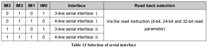
Mode Selection for SPI Interface
From the above figure, it can be seen that ST7789 uses the IM[3:0] pins to select the configuration of Interface I/II and 3/4-line, enabling four different interface modes. The following diagram shows the pin description for the ST7789 SPI interface:
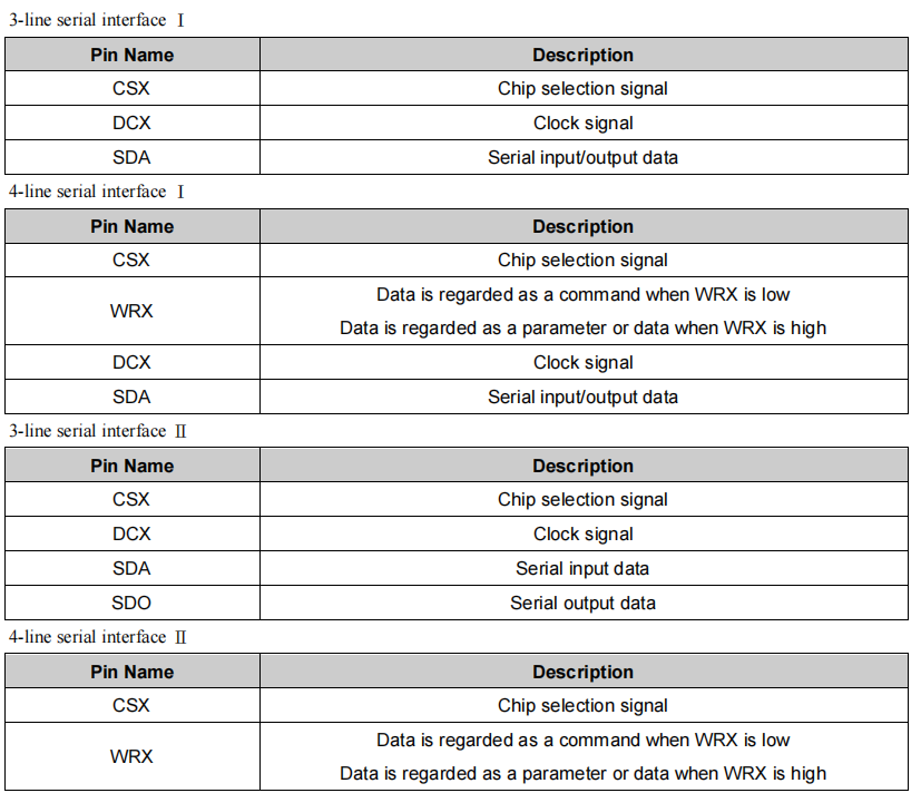
Pin Description for SPI Interface
Note: SPI pin names: CS, SCK (SCL), SDA (MOSI), SDO (MISO), DC (RS).
Interface I/II Mode
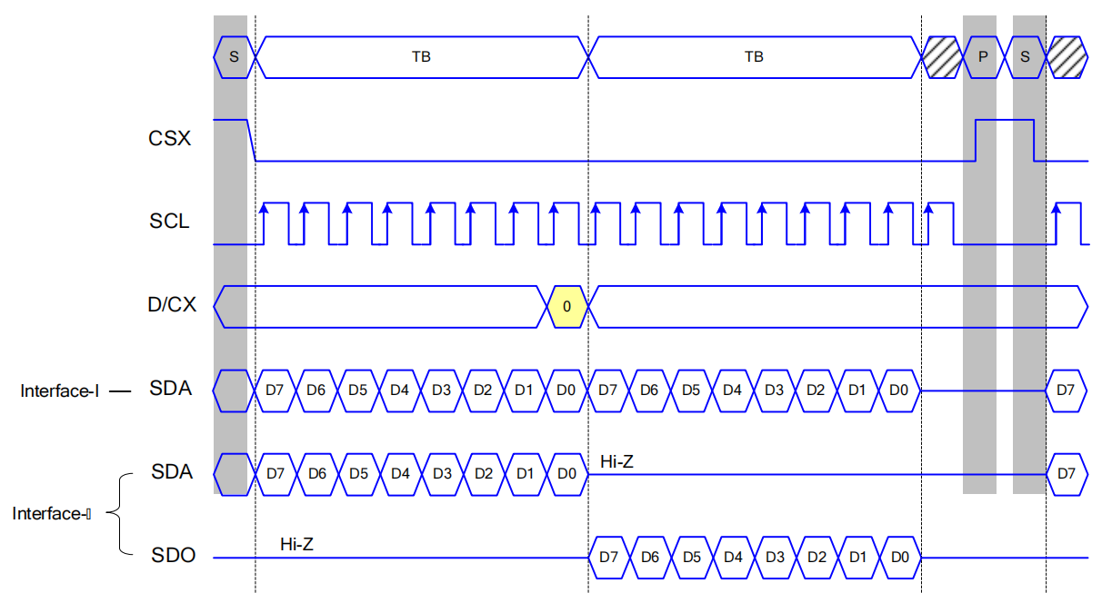
Timing Diagram Comparison for Interface I/II Mode (4-line)
From the diagram, it can be observed that the main difference between Interface I and Interface II lies in whether only one data line is used for both data read and write (such as only using MOSI).
Mode |
Whether only one data line is used for data read and write |
ESP Support |
|---|---|---|
Interface I |
Yes |
Yes |
Interface II |
No |
Yes |
3/4-line Mode
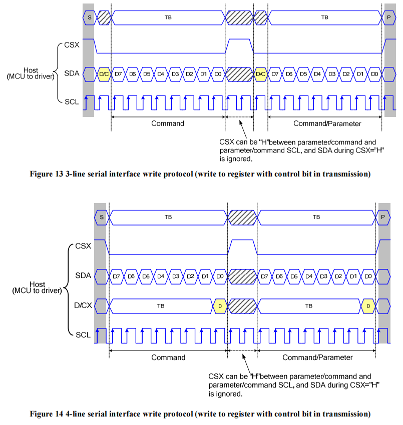
Timing Diagram Comparison for 3/4-line Mode (Interface I)
From the diagram, it can be seen that the main difference between “3-line” and “4-line” lies in whether the D/C signal line is used.
Mode |
Whether D/C signal line is used |
ESP Support |
|---|---|---|
3-line |
No |
No |
4-line |
Yes |
Yes |
Note
3-linemode is sometimes referred to as3-wireor9-bitmode.While ESP’s SPI peripheral does not support the LCD’s
3-linemode, it can be implemented through software emulation. For details, please refer to the esp_lcd_panel_io_additions component. This is typically used for initializing RGB LCDs.
SPI LCD Driving Process:
The SPI LCD driver process can be roughly divided into three parts: initializing the interface device, porting driver components, and initializing the LCD device.
Initialization Interface Device
Initializing the interface device involves first initializing the bus and then creating the interface device. The following is based on the spi_lcd_touch example from ESP-IDF release/v6.0, demonstrating how to initialize an SPI interface device.
Initializing the Bus
Example Code:
#include "driver/spi_master.h"            // Dependent header files
#include "esp_check.h"

spi_bus_config_t buscfg = {
    .sclk_io_num = EXAMPLE_PIN_NUM_SCLK,  // IO number for connecting LCD SCK (SCL) signal
    .mosi_io_num = EXAMPLE_PIN_NUM_MOSI,  // IO number for connecting LCD MOSI (SDO, SDA) signal
    .miso_io_num = EXAMPLE_PIN_NUM_MISO,  // IO number for connecting LCD MISO (SDI) signal; set to `-1` if data read from LCD is not required
    .quadwp_io_num = -1,                  // Must be set to `-1`
    .quadhd_io_num = -1,                  // Must be set to `-1`
    .max_transfer_sz = EXAMPLE_LCD_H_RES * 80 * sizeof(uint16_t), // Represents the maximum number of bytes allowed for a single SPI transfer; usually set to the screen size
};
ESP_ERROR_CHECK(spi_bus_initialize(LCD_HOST, &buscfg, SPI_DMA_CH_AUTO));
                                          // The 1st parameter represents the SPI host ID used, consistent with subsequent interface device creation
                                          // The 3rd parameter represents the DMA channel number used, set to `SPI_DMA_CH_AUTO` by default
If multiple devices are using the same SPI bus simultaneously, the bus only needs to be initialized once.
The following are explanations for some configuration parameters:
If the LCD driver IC is configured in Interface-I mode, only set
mosi_io_numas the data line IO, and setmiso_io_numto -1.The SPI driver checks the size of the input data before transmitting data. If the number of bytes for a single transfer exceeds
max_transfer_sz, an error will be reported. However, the maximum number of bytes allowed for a single DMA transfer depends not only onmax_transfer_szbut is also limited by SPI_LL_DATA_MAX_BIT_LEN in ESP-IDF (different ESP series have different values), i.e., satisfyingmax_transfer_sz <= MIN(max_transfer_sz, (SPI_LL_DATA_MAX_BIT_LEN / 8)). Since the esp_lcd driver checks in advance whether the input data size exceeds the limit and performs packetization if it does, controlling SPI for multiple transfers, max_transfer_sz is usually set to the screen size.
Creating the Interface Device
Example Code:
#include "esp_lcd_panel_io.h"       // Header file dependency

static bool example_on_color_trans_dome(esp_lcd_panel_io_handle_t panel_io, esp_lcd_panel_io_event_data_t *edata, void *user_ctx)
{
        /* Callback function when color data transmission is completed; perform operations here if needed */

    return false;
}

esp_lcd_panel_io_handle_t io_handle = NULL;
esp_lcd_panel_io_spi_config_t io_config = {
    .dc_gpio_num = EXAMPLE_PIN_NUM_LCD_DC,     // IO number connected to the LCD DC (RS) signal; set to `-1` to disable
    .cs_gpio_num = EXAMPLE_PIN_NUM_LCD_CS,     // IO number connected to the LCD CS signal; set to `-1` to disable
    .pclk_hz = EXAMPLE_LCD_PIXEL_CLOCK_HZ,     // SPI clock frequency (Hz), ESP supports up to 80M (SPI_MASTER_FREQ_80M)
                                               // Determine the maximum value based on the LCD driver IC data sheet
    .lcd_cmd_bits = EXAMPLE_LCD_CMD_BITS,      // Number of bits per LCD command, should be a multiple of 8
    .lcd_param_bits = EXAMPLE_LCD_PARAM_BITS,  // Number of bits per LCD parameter, should be a multiple of 8
    .spi_mode = 0,                             // SPI mode (0-3); determine based on the LCD driver IC data sheet and hardware configuration (e.g., IM[3:0])
    .trans_queue_depth = 10,                   // Queue depth for SPI device data transmission; usually set to 10
    .on_color_trans_done = example_on_color_trans_dome,   // Callback function after a single call to `esp_lcd_panel_draw_bitmap()` completes transmission
    .user_ctx = &example_user_ctx,             // User parameter passed to the callback function
    .flags = {     // Parameters related to SPI timing; determine based on the LCD driver IC data sheet and hardware configuration
        .sio_mode = 0,     // Read and write data through one data line (MOSI); 0: Interface I type, 1: Interface II type
    },
};
ESP_ERROR_CHECK(esp_lcd_new_panel_io_spi((esp_lcd_spi_bus_handle_t)LCD_HOST, &io_config, &io_handle));

/* The following functions can also be used to register the callback function for color data transmission completion events */
// const esp_lcd_panel_io_callbacks_t cbs = {
//     .on_color_trans_done = example_on_color_trans_dome,
// };
// esp_lcd_panel_io_register_event_callbacks(io_handle, &cbs, &example_user_ctx);
Once the SPI bus is initialized, you can create the corresponding interface device. Each interface device corresponds to an SPI master device.
Note:: For a more detailed explanation of the ``SPI`` interface configuration parameters, please refer to the ESP-IDF Programming Guide.
By creating the interface device, you can obtain a handle of data type esp_lcd_panel_io_handle_t, which allows you to use the following General Interface APIs to send commands and image data to the LCD driver IC:
esp_lcd_panel_io_tx_param(): Used to send a single command and its associated parameters to the LCD. Internally, it uses thespi_device_polling_transmit()function for data transmission, and using this function will wait for the data transmission to complete before returning.
esp_lcd_panel_io_tx_color(): Used to send a single command and image data for LCD screen refreshing. Inside the function, it usesspi_device_polling_transmit()to send commands and a small amount of parameters, and then usesspi_device_queue_trans()to send large amounts of image data in packets. The size of each packet is limited by the maximum number of bytes allowed for a single DMA transfer in SPI. This function pushes relevant data, including the image buffer address, into the queue, and the depth of the queue is specified by thetrans_queue_depthparameter. Once the data is successfully pushed into the queue, the function immediately returns. Therefore, if you plan to modify the same image buffer in subsequent operations, you need to register a callback function to determine whether the previous transfer has been completed. If you don’t do this, modifying on an incomplete transfer may lead to display errors due to data corruption.
Porting Driver Components
The basic principles of porting an SPI LCD driver component include the following three points:
Sending specified format commands and parameters based on the interface device handle of data type
esp_lcd_panel_io_handle_t.Implementing and creating an LCD device, then implementing various functions in the esp_lcd_panel_t structure through the registration of callback functions.
Implementing a function to provide an LCD device handle of data type
esp_lcd_panel_handle_t, enabling the application to use LCD General APIs to operate the LCD device.
The following is an explanation of the implementation of various functions in esp_lcd_panel_handle_t and their corresponding relationships with LCD General APIs:
Function |
LCD General APIs |
Implementation Explanation |
|---|---|---|
reset() |
esp_lcd_panel_reset() |
If the device is connected to a reset pin, perform a hardware reset through that pin. Otherwise, perform a software reset using the command |
init() |
esp_lcd_panel_init() |
Initialize the LCD device by sending a series of commands and parameters. |
del() |
esp_lcd_panel_del() |
Release resources occupied by the driver, including allocated memory and used IO. |
draw_bitmap() |
esp_lcd_panel_draw_bitmap() |
First, send the starting and ending coordinates of the image using the commands |
mirror() |
esp_lcd_panel_mirror() |
Set whether to mirror the X-axis and Y-axis of the screen using the command |
swap_xy() |
esp_lcd_panel_swap_xy() |
Set whether to swap the X-axis and Y-axis of the screen using the command |
set_gap() |
esp_lcd_panel_set_gap() |
Modify the starting and ending coordinates for drawing through software to achieve drawing offset. |
invert_color() |
esp_lcd_panel_invert_color() |
Invert the color data of pixels using the commands |
disp_on_off() |
esp_lcd_panel_disp_on_off() |
Turn the screen display on or off using the commands |
For most SPI LCDs, their driver IC commands and parameters are compatible with the explanations provided above. Therefore, porting can be completed through the following steps:
Choose an SPI LCD driver component in LCD Driver Components that is similar to the model you are targeting.
Consult the data sheet of the target LCD driver IC to verify the consistency of commands and parameters within each function of the selected component. If inconsistencies are identified, make appropriate modifications to the relevant code.
Although the models of the LCD driver IC might be identical, different screens require specific configurations through initialization commands provided by their respective manufacturers. Therefore, you need to modify the commands and parameters sent in the
init()function. These initialization commands are usually stored in a static array in a specific format. Additionally, be careful not to include some special commands in the initialization commands, such asLCD_CMD_COLMOD (3Ah)andLCD_CMD_MADCTL (36h), as these commands are managed and used by the driver component.Use the character search and replace feature in your editor to replace the LCD driver IC name in the component with the target name. For example, replace
gc9a01withst77916.
Initializing the LCD Device
The following is an example code explanation using GC9A01:
#include "esp_lcd_panel_vendor.h"   // Dependent header files
#include "esp_lcd_panel_ops.h"
#include "esp_lcd_gc9a01.h"         // Header file of the target driver component

/**
* Used to store the initialization commands and parameters of the LCD driver IC
*/
// static const gc9a01_lcd_init_cmd_t lcd_init_cmds[] = {
// //  {cmd, { data }, data_size, delay_ms}
//     {0xfe, (uint8_t []){0x00}, 0, 0},
//     {0xef, (uint8_t []){0x00}, 0, 0},
//     {0xeb, (uint8_t []){0x14}, 1, 0},
//     ...
// };

/* Create the LCD device */
esp_lcd_panel_handle_t panel_handle = NULL;
// const gc9a01_vendor_config_t vendor_config = {  // Used to replace the initialization commands and parameters in the driver component
//     .init_cmds = lcd_init_cmds,
//     .init_cmds_size = sizeof(lcd_init_cmds) / sizeof(gc9a01_lcd_init_cmd_t),
// };
esp_lcd_panel_dev_config_t panel_config = {
    .reset_gpio_num = EXAMPLE_PIN_NUM_LCD_RST,    // Connect the IO number of the LCD reset signal, set to `-1` to indicate not using
    .rgb_ele_order = LCD_RGB_ELEMENT_ORDER_RGB,   // Element order of pixel color (RGB/BGR),
                                                  // Usually controlled by the command `LCD_CMD_MADCTL (36h)`
    .bits_per_pixel = EXAMPLE_LCD_BIT_PER_PIXEL,  // Bit depth of the color format (RGB565: 16, RGB666: 18),
                                                  // usually controlled by the command `LCD_CMD_COLMOD (3Ah)`
    // .vendor_config = &vendor_config,           // Used to replace the initialization commands and parameters in the driver component
};
ESP_ERROR_CHECK(esp_lcd_new_panel_gc9a01(io_handle, &panel_config, &panel_handle));

/* Initialize the LCD device */
ESP_ERROR_CHECK(esp_lcd_panel_reset(panel_handle));
ESP_ERROR_CHECK(esp_lcd_panel_init(panel_handle));
// ESP_ERROR_CHECK(esp_lcd_panel_invert_color(panel_handle, true));   // Use these functions as needed
// ESP_ERROR_CHECK(esp_lcd_panel_mirror(panel_handle, true, true));
// ESP_ERROR_CHECK(esp_lcd_panel_swap_xy(panel_handle, true));
// ESP_ERROR_CHECK(esp_lcd_panel_set_gap(panel_handle, 0, 0));
ESP_ERROR_CHECK(esp_lcd_panel_disp_on_off(panel_handle, true));
First, create an LCD device and obtain a handle of data type esp_lcd_panel_handle_t using the ported driver component. Then, use the LCD General APIs to initialize the LCD device.
Here are some explanations regarding the use of the esp_lcd_panel_draw_bitmap() function to refresh images on an SPI LCD:
The number of bytes of the image buffer passed to this function can be greater than
max_transfer_sz. In this case, theesp_lcddriver internally performs packetization based on the maximum number of bytes allowed for a single DMA transfer in SPI.Since this function transfers image data using DMA, which means that after the function call, data is still being transferred via DMA, it is not allowed to modify the currently used buffer area (such as rendering with LVGL). Therefore, it is necessary to determine whether the previous transfer has completed through bus initialization or by calling the callback functions registered with
esp_lcd_panel_io_register_event_callbacks().As the SPI driver currently does not support directly transferring data from PSRAM using DMA, it internally checks whether the data is stored in PSRAM. If it is, it will copy it to SRAM before transferring. Therefore, it is recommended to use SRAM as the image buffer for transfer (such as a buffer used for LVGL rendering). Otherwise, directly transferring large image data from PSRAM may lead to insufficient SRAM.