EspRFTestTool Toolkit
The EspRFTestTool toolkit is an RF test tool provided by Espressif. It contains EspRFTestTool, DownloadTool, and PowerLimitTool.
EspRFTestTool: Used to perform RF tests
DownloadTool: Used to download the firmware required for RF tests
PowerLimitTool: Used to generate customized phy_init_data firmware
Download Link: EspRFTestTool Package
The zip file not only includes the EspRFTestTool toolkit but also contains all the necessary firmware for RF Test Items, allowing users familiar with the testing process to directly use the firmware for testing.
Note
In this document, the EspRFTestTool toolkit refers to the collection of the three tools, while the EspRFTestTool refers to this single tool.
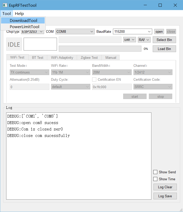
EspRFTestTool
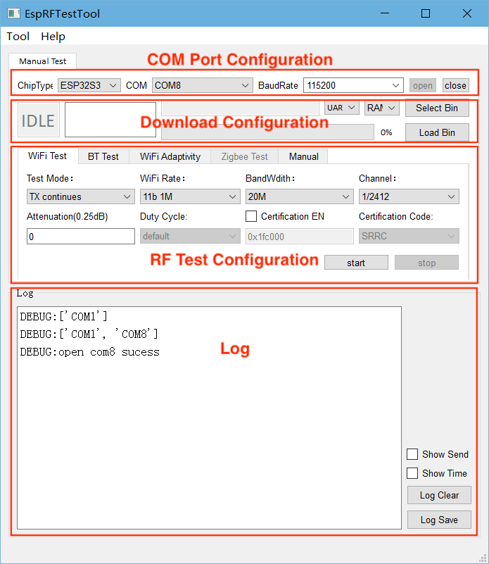
The main interface of the EspRFTestTool toolkit is the EspRFTestTool, which includes the COM Port Configuration area, the Download Configuration area, the RF Test Configuration area, and the Log window.
EspRFTestTool
COM Port Configuration Area
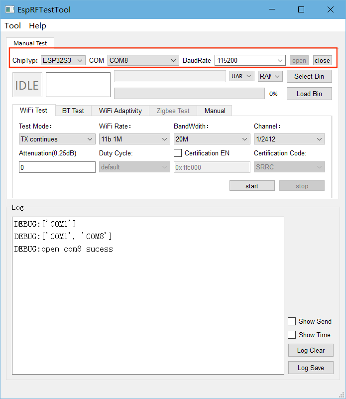
EspRFTestTool COM Port Configuration Area
ChipType: Select the chip;
COM: Select the serial port number;
BaudRate: Select the baud rate;
Open: Open the serial port;
Close: Close the serial port.
After configuring the serial port, you can perform quick flashing and RF tests.
Download Configuration Area
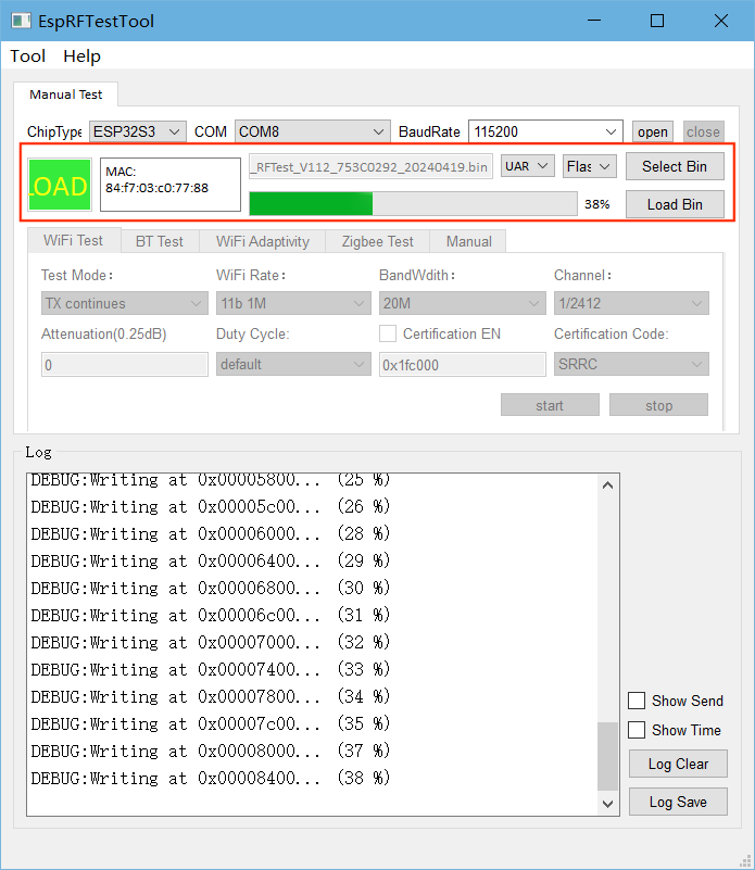
EspRFTestTool Download Configuration Area
Generally, the DownloadTool is used to download the firmware required for RF tests. However, for some simple firmware, such as non-signaling test firmware and adaptivity test firmware, EspRFTestTool can be used for quick flashing.
Pull down the Boot pin and re-power the chip to enter download mode;
By default, flashing is conducted through
UART;Select
flashto download to the flash;Click
Select Binto select the bin file to be flashed;Click
Load Binto start flashing;After flashing is completed, pull up the Boot pin and re-power the chip to enter operation mode.
RF Test Configuration Area
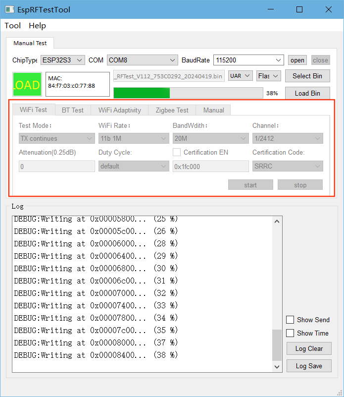
EspRFTestTool RF Test Configuration Area
After flashing the firmware, you can perform the corresponding RF tests:
Wi-Fi Test: Used for Wi-Fi Non-Signaling Test;
BT Test: Used for Bluetooth and Bluetooth LE Non-Signaling Test;
Wi-Fi Adaptivity: Used for Wi-Fi Adaptivity Test;
Zigbee Test: Used for 802.15.4 Non-Signaling Test;
Manual: Used to enter serial port commands.
For specific parameter configuration, please refer to the corresponding RF test document.
Log Window
The Log window is used to display the status of the tool. To view the log printed via the chip serial port, please use a general serial port assistant, such as SerialPortUtility.
DownloadTool
Click Tool in the toolbar and select DownloadTool to enter the DownloadTool interface.
Entry to DownloadTool
Follow the steps below to flash the firmware:
Set the
Chip Type,COM Port, andBaud Rate. Then, clickOpento open the serial port;Select
flashto download to the flash;Select the firmware and flash it to the specified address;
Check whether the chip has entered download mode. If yes, click
Start Loadto start flashing. After flashing is completed, theSUCCsign shows up;After flashing is completed, click
Closeto close the serial port.
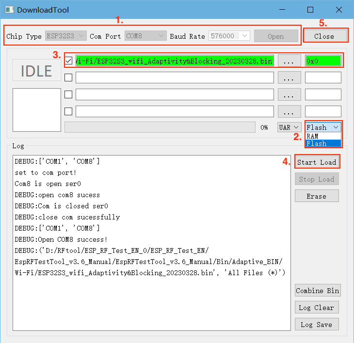
DownloadTool Interface
Note
How to check whether the chip has entered download mode:
Close the serial port of DownloadTool and open a general serial port assistant, such as SerialPortUtility;
Configure the serial port number and baud rate, pull down the Boot pin, re-power the chip, and the serial port assistant will print the log like
waiting for download;Close the serial port assistant, open DownloadTool, and start flashing;
After the flashing is completed, pull up the Boot pin, and re-power the chip to enter operation mode. If there are any abnormal behaviors, use the serial port assistant to check.
Note
By default, DownloadTool flashes to RAM. To specify a flash address, you need to switch to flashing to flash first.
PowerLimitTool
PowerLimitTool generates single-country and multi-country phy_init_bin files by configuring Wi-Fi output power to ensure your products meet the regulatory requirements of different countries or regions.
Note
The following methods can be used to limit Wi-Fi power. If multiple methods are used together, the minimum power value will be taken:
Use the API (
esp_wifi_set_max_tx_power) to limit the maximum output power.Configure
Max Wi-Fi TX Powerin Menuconfig, which serves the same function as the API mentioned above and can limit the maximum output power.Use the
Phy Init Binfunction to modify the phy_init_data.h file in ESP-IDF.Use the
Phy Init Binfunction to generate the phy_init_data.bin file by referring to the introduction in this document.
Under the main interface of EspRFTestTool, click Tool, and select PowerLimitTool from the dropdown box to open PowerLimitTool.
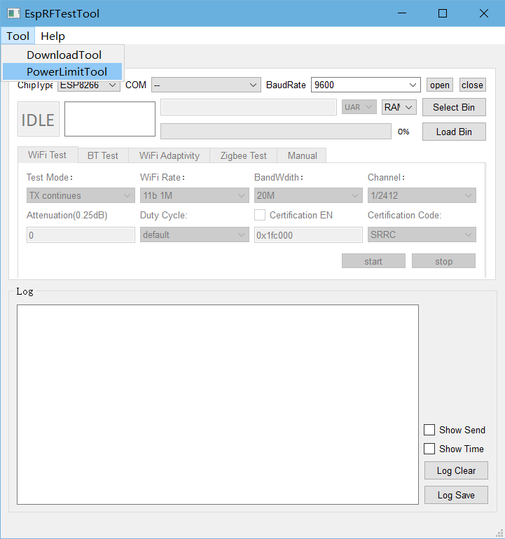
Entry to PowerLimitTool
In the main interface of PowerLimitTool, click the
Chipdropdown box to view the chips supported by the tool and select a chip (This section takes ESP32-C3 as an example).
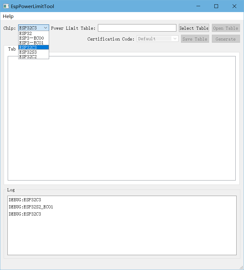
PowerLimitTool Main Interface
Click
Select Tableand select the TX Power Setting table for your chip.
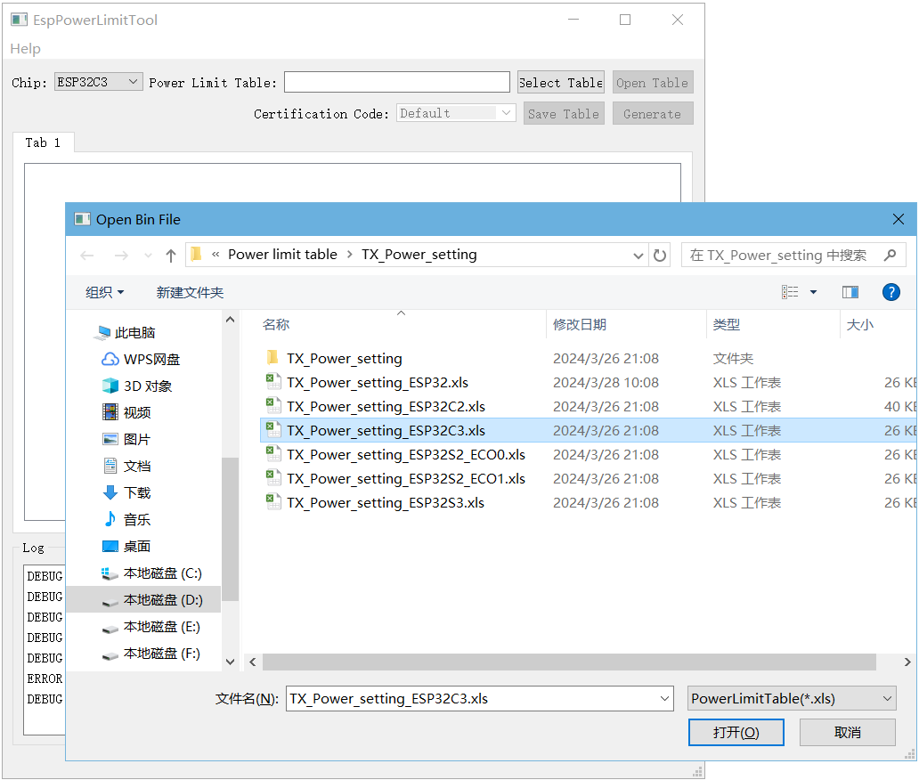
Importing TX Power Setting Table
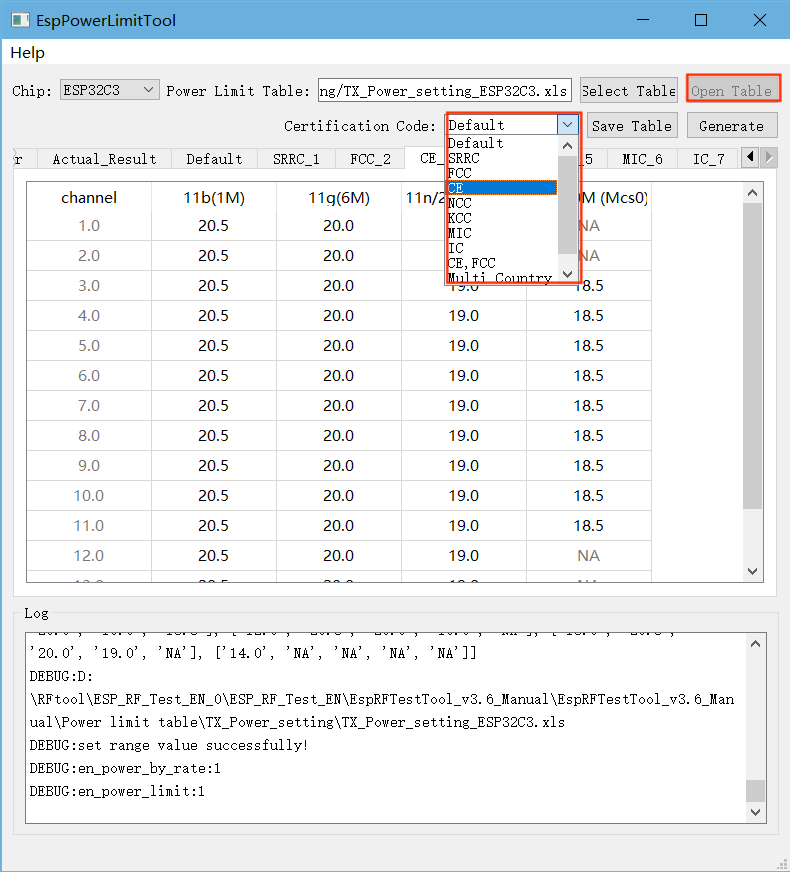
Click
Open Table, modify the power value in the corresponding country code table, and clickSave Table.
Note
How to modify power values:
Fill in the power value based on the certification result (the certification provides the power attenuation value) (Power value = Target power - Attenuation value/4).
If
Actual_Resultis modified, the Target power in the above formula needs to be changed toActual_Result.Adding or deleting table content is not allowed. For example, FCC only supports channels 1 – 11, so it is recommended to keep the power values of channels 12 – 13 in this table the same as channel 11 instead of deleting them;
Except for low and high channels, the power values of other channels should be set to the same as the middle channel;
The NA section cannot be modified. If the
Certification Codecannot be selected from the dropdown box , it indicates that the table has been modified and needs to be restored.
After saving the power changes, select the required certification from the
Certification Codedropdown, then clickGenerateto generate the phy_init_bin file for the corresponding country code.
Modifying TX_Power_Setting
Note
Description of TX Power Setting Table parameters:
Config_Switch: Enable
Power_By_RateandPower_Limit. Both are set toYesby default, indicating they can be adjusted.PowerByRate_TargetPower: Target power for each rate. It is recommended to keep the default value.
Country_Table: Currently supported countries (regions). It is extensible.
Actual_Result: Actual power of the module. The target power is used by default.
Default: Power configuration in the “Default” country code, usually used to identify the power configuration before setting the country code.
SRRC_1: Power configuration of the “SRRC” country code, applicable to Mainland China.
FCC_2: Power configuration of the “FCC” country code, applicable to the United States.
CE_3: Power configuration of the “CE” country code, applicable to Europe.
NCC_4: Power configuration of the “NCC” country code, applicable to Taiwan.
KCC_5: Power configuration of the “KCC” country code, applicable to South Korea.
MIC_6: Power configuration of the “MIC” country code, applicable to Japan.
IC_7: Power configuration of the “IC” country code, applicable to Canada.
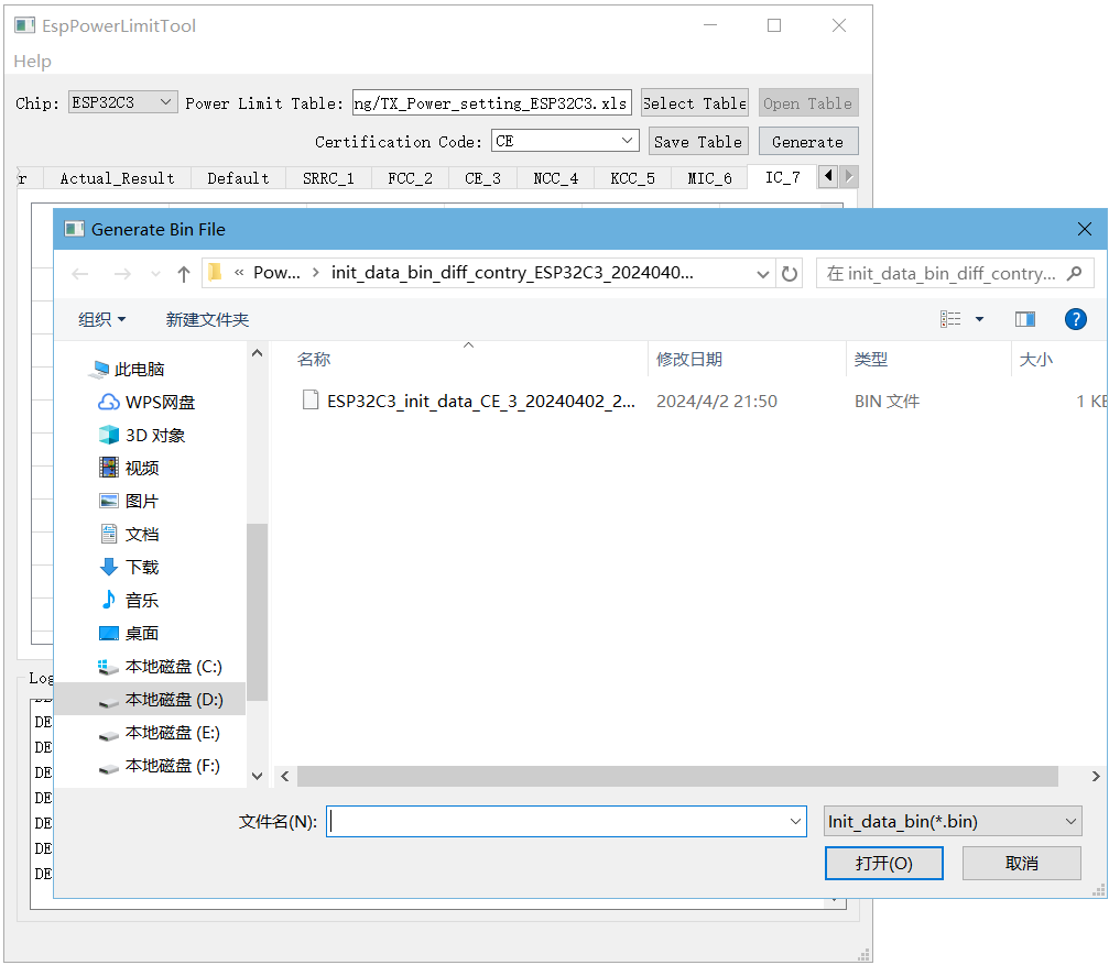
Generate phy_init_bin File
Note
The dropdown list of Certification Code includes options for a single certification,
Multiple Country, andCustom.Selecting a single certification will generate a single phy_init_bin file for that certification, which contains a total of 128 bytes except the verification control information.
Selecting
Multiple Countrywill generate Combined phy_init_bin files, including a Default bing file and seven others for SRRC, FCC, CE, NCC, KCC, MIC, and IC. The combined files contain 8*128 bytes.Selecting Custom will generate a single or multiple certification bin files based on your choice.
Verify whether phy_init_bin is effective using Non-Signaling or Signaling Test. Taking Non-Signaling Test as an example, first use the DownloadTool to download the generated phy_init_bin file to the testing product.
Select
DownloadToolfromTooldropdown list to enter theDownloadToolinterface.Flash the phy_init_bin file and corresponding RF test firmware to
flashby referring to the instructions stated DownloadTool.The flash address for phy_init_bin is
0x1fc000and the flash address for the RF test firmware ESP32 RF Non-Signaling Test Firmware is 0x1000.
Note
Regarding the Signaling Test, you can simply replace the original phy_init_bin. Please refer to the relevant documents in RF Test Items.
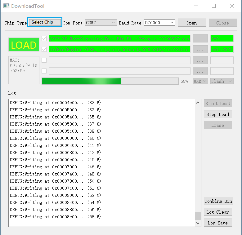
Flash phy_init_bin File
Use a Wi-Fi tester to measure the output power and check whether phy_init_bin is effective.
Open EspRFTestTool.
Select corresponding
ChipType,COM,BaudRate, and clickOpento open the serial port.Open the
WiFi Testtab, and selectTest Mode,Rate,BandWidthandChannel.Set
Attenuationto 0, andDuty Cycleto 10%.With
Certification ENunchecked, i.e., Phy init not enabled, the tool tests the initial performance of modules.With
Certification ENchecked, i.e., Phy init enabled, the tool tests the performance for certification.The default address for flashing phy_init_bin is 0x1fc000. If the flashing address changes, update it here.
For Multiple Country, you can select the certification country codes it includes in the
Certification Code.
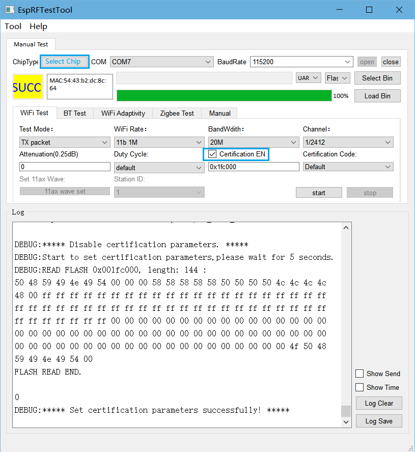
RF Test Configuration
Typical Average Output Power of ESP32
Rates |
Typical Average Output Power (dBm) |
|---|---|
11b 1 Mbps |
19.5 |
11b 11 Mbps |
19.5 |
11g 6 Mbps |
18 |
11g 54 Mbps |
14 |
11n-20 MCS0 |
18 |
11n-20 MCS7 |
13 |
11n-40 MCS0 |
18 |
11n-40 MCS7 |
13 |