Flight Control System
Startup Process
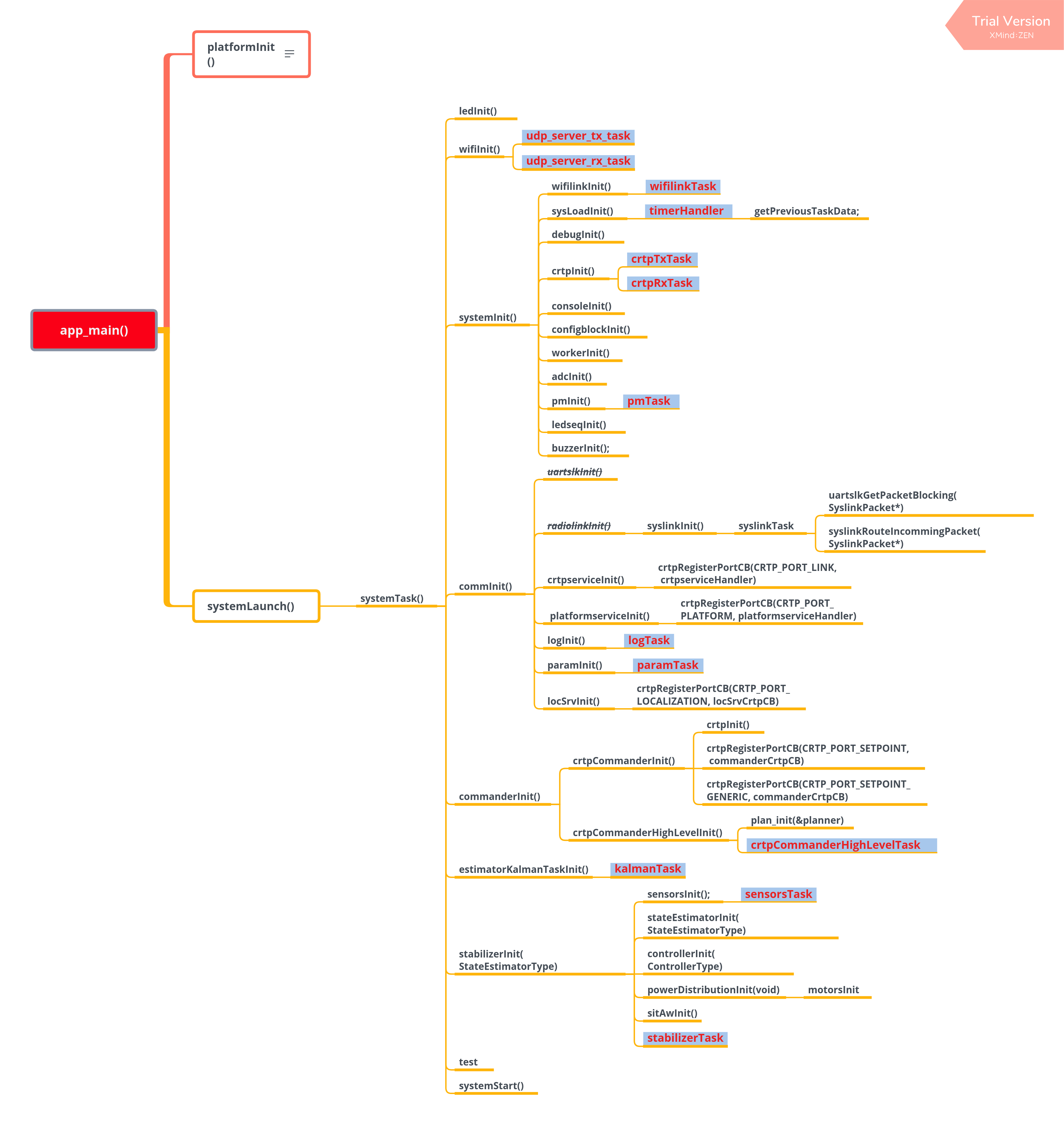
For source file, please check start_from_app_main.
Task Management
Tasks
The following TASKs are started when the system is operating properly.
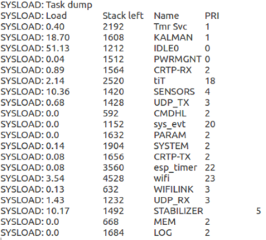
Task Dump
Load: CPU occupancy
Stack Left: remaining stack space
Name: task name
PRI: task priority
TASKs are described as follows:
PWRMGNT: monitor system voltage
CMDHL: application layer - process advanced commands based on CRTP protocol
CRTP-RX: protocol layer - decode CRTP flight protocol
CRTP-TX: protocol layer - decode CRTP flight protocol
UDP-RX: transport layer - receive UDP packet
UDP-TX: Transport Layer - send UDP packet
WIFILINK: work with CRTP protocol layer and UDP transport layer
SENSORS: read and pre-process sensor data
KALMAN: estimate the drone’s status according to sensor data, including the drone’s angle, angular velocity, and spatial position. This TASK consumes a large amount of CPU resources on the ESP chip and users should be careful about its priority allocation.
PARAM: modify variables remotely according to CRTP protocol
LOG: monitor variables on real-time according to CRTP protocol
MEM: modify memory remotely according to CRTP protocol
STABILIZER: self stabilize its thread, and control the process of flight control program
SYSTEM: control system initialization and self-test process
Configure Task Stack Size
Users can modify the stack size in components/config/include/config.h, or modify BASE_STACK_SIZE in menucfg. When the target is ESP32, you can adjust the BASE_STACK_SIZE to 2048, to avoid memory overlapping. When the target is ESP32-S2, modify the value to 1024.
//Task stack size
#define SYSTEM_TASK_STACKSIZE         (4* configBASE_STACK_SIZE)
#define ADC_TASK_STACKSIZE            configBASE_STACK_SIZE
#define PM_TASK_STACKSIZE             (2*configBASE_STACK_SIZE)
#define CRTP_TX_TASK_STACKSIZE        (2*configBASE_STACK_SIZE)
#define CRTP_RX_TASK_STACKSIZE        (2* configBASE_STACK_SIZE)
#define CRTP_RXTX_TASK_STACKSIZE      configBASE_STACK_SIZE
#define LOG_TASK_STACKSIZE            (2*configBASE_STACK_SIZE)
#define MEM_TASK_STACKSIZE            (1 * configBASE_STACK_SIZE)
#define PARAM_TASK_STACKSIZE          (2*configBASE_STACK_SIZE)
#define SENSORS_TASK_STACKSIZE        (2 * configBASE_STACK_SIZE)
#define STABILIZER_TASK_STACKSIZE     (2 * configBASE_STACK_SIZE)
#define NRF24LINK_TASK_STACKSIZE      configBASE_STACK_SIZE
#define ESKYLINK_TASK_STACKSIZE       configBASE_STACK_SIZE
#define SYSLINK_TASK_STACKSIZE        configBASE_STACK_SIZE
#define USBLINK_TASK_STACKSIZE        configBASE_STACK_SIZE
#define WIFILINK_TASK_STACKSIZE        (2*configBASE_STACK_SIZE)
#define UDP_TX_TASK_STACKSIZE   (2*configBASE_STACK_SIZE)
#define UDP_RX_TASK_STACKSIZE   (2*configBASE_STACK_SIZE)
#define UDP_RX2_TASK_STACKSIZE   (1*configBASE_STACK_SIZE)
#define PROXIMITY_TASK_STACKSIZE      configBASE_STACK_SIZE
#define EXTRX_TASK_STACKSIZE          configBASE_STACK_SIZE
#define UART_RX_TASK_STACKSIZE        configBASE_STACK_SIZE
#define ZRANGER_TASK_STACKSIZE        (1* configBASE_STACK_SIZE)
#define ZRANGER2_TASK_STACKSIZE       (2* configBASE_STACK_SIZE)
#define FLOW_TASK_STACKSIZE           (2* configBASE_STACK_SIZE)
#define USDLOG_TASK_STACKSIZE         (1* configBASE_STACK_SIZE)
#define USDWRITE_TASK_STACKSIZE       (1* configBASE_STACK_SIZE)
#define PCA9685_TASK_STACKSIZE        (1* configBASE_STACK_SIZE)
#define CMD_HIGH_LEVEL_TASK_STACKSIZE (1* configBASE_STACK_SIZE)
#define MULTIRANGER_TASK_STACKSIZE    (1* configBASE_STACK_SIZE)
#define ACTIVEMARKER_TASK_STACKSIZE   configBASE_STACK_SIZE
#define AI_DECK_TASK_STACKSIZE        configBASE_STACK_SIZE
#define UART2_TASK_STACKSIZE          configBASE_STACK_SIZE
Configure Task Priority
The priority of system tasks can be configured in components/config/include/config.h. ESP32, for its dual-core advantage, has more computing resources than ESP32-S2, therefore, its time-consuming KALMAN_TASK can be set to a higher priority. But if the target is ESP32-S2, please lower the priority of the KALMAN_TASK, otherwise task watchdog will be triggered due to the failure of releasing enough CPU resources.
//Task priority: the higher the number, the higher the priority.
#define STABILIZER_TASK_PRI     5
#define SENSORS_TASK_PRI        4
#define ADC_TASK_PRI            3
#define FLOW_TASK_PRI           3
#define MULTIRANGER_TASK_PRI    3
#define SYSTEM_TASK_PRI         2
#define CRTP_TX_TASK_PRI        2
#define CRTP_RX_TASK_PRI        2
#define EXTRX_TASK_PRI          2
#define ZRANGER_TASK_PRI        2
#define ZRANGER2_TASK_PRI       2
#define PROXIMITY_TASK_PRI      0
#define PM_TASK_PRI             0
#define USDLOG_TASK_PRI         1
#define USDWRITE_TASK_PRI       0
#define PCA9685_TASK_PRI        2
#define CMD_HIGH_LEVEL_TASK_PRI 2
#define BQ_OSD_TASK_PRI         1
#define GTGPS_DECK_TASK_PRI     1
#define LIGHTHOUSE_TASK_PRI     3
#define LPS_DECK_TASK_PRI       5
#define OA_DECK_TASK_PRI        3
#define UART1_TEST_TASK_PRI     1
#define UART2_TEST_TASK_PRI     1
//if task watchdog triggered, KALMAN_TASK_PRI should set lower or set lower flow frequency
#ifdef CONFIG_IDF_TARGET_ESP32
  #define KALMAN_TASK_PRI         2
  #define LOG_TASK_PRI            1
  #define MEM_TASK_PRI            1
  #define PARAM_TASK_PRI          1
#else
  #define KALMAN_TASK_PRI         1
  #define LOG_TASK_PRI            2
  #define MEM_TASK_PRI            2
  #define PARAM_TASK_PRI          2
#endif

#define SYSLINK_TASK_PRI        3
#define USBLINK_TASK_PRI        3
#define ACTIVE_MARKER_TASK_PRI  3
#define AI_DECK_TASK_PRI        3
#define UART2_TASK_PRI          3
#define WIFILINK_TASK_PRI       3
#define UDP_TX_TASK_PRI         3
#define UDP_RX_TASK_PRI         3
#define UDP_RX2_TASK_PRI        3
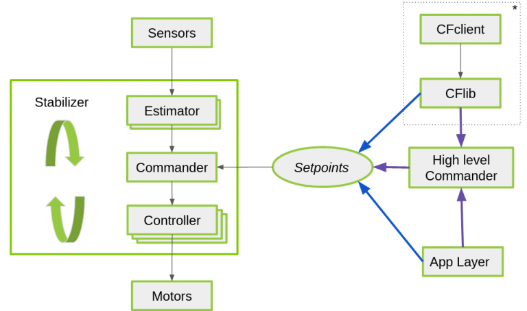
Key Tasks
Except the system default enabled tasks, such as Wi-Fi TASK, the task with the highest priority is STABILIZER_TASK, highlighting the importance of this task. STABILIZER_TASK controls the entire process from sensor data reading, attitude calculation, target receiving, to final motor power output, and drives the algorithms at each stage.
stabilizerTask Process
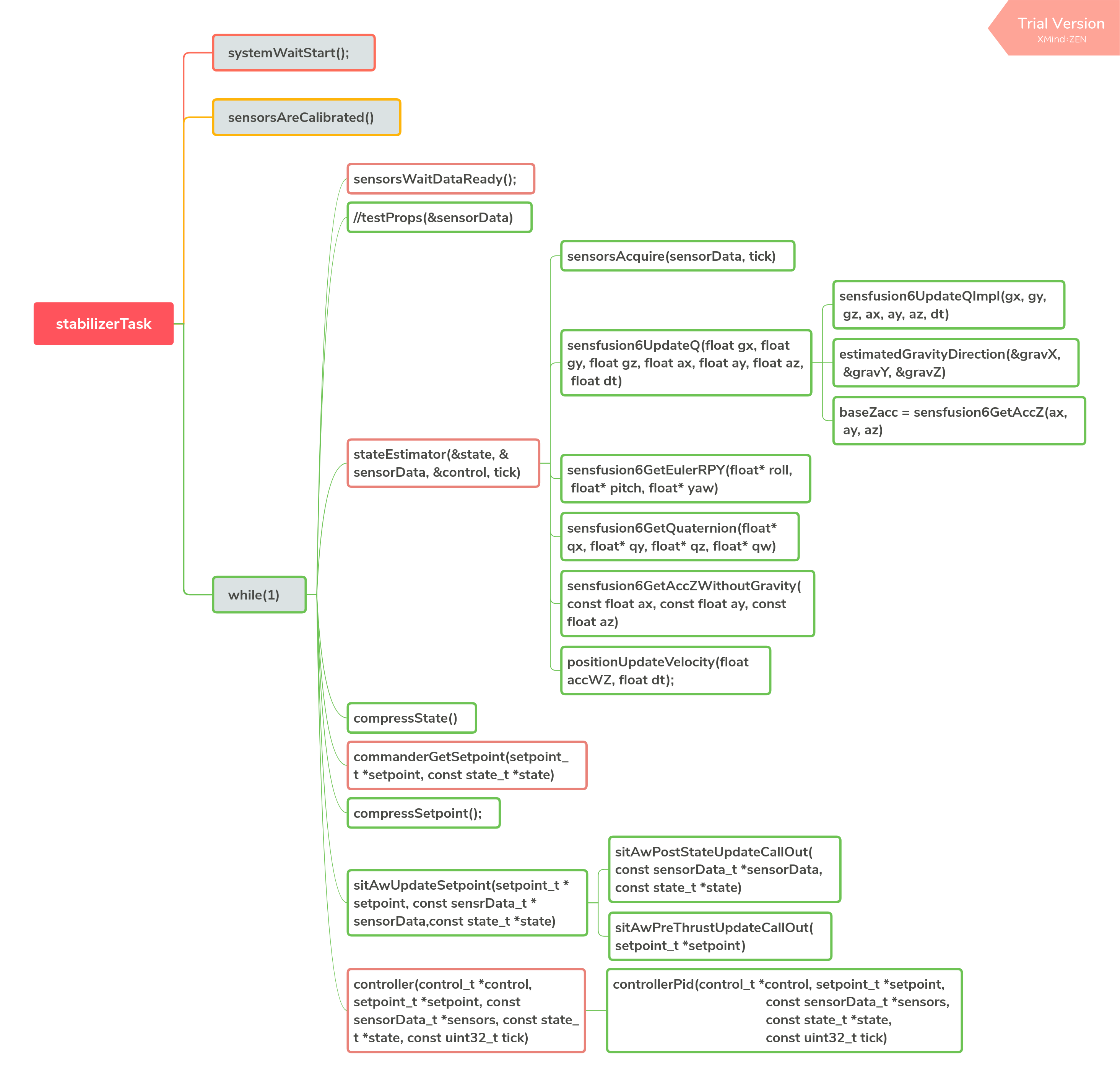
stabilizerTask
Sensor Driver
The sensor driver code can be found in components\drivers. drivers applies a file structure similar to that used in esp-iot-solution. In such structure, drivers are classified by the bus they belong to, including i2c_devices, spi_devices, and general. For more information, please refer to Drivers.
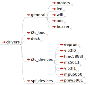
Drivers File Structure
Sensor Hardware Abstraction
components\core\crazyflie\hal\src\sensors.c provides hardware abstraction for the sensors. Users are free to combine sensors to interact with upper-level application by implementing the sensor interfaces defined by the hardware abstraction layer.
typedef struct {
  SensorImplementation_t implements;
  void (*init)(void);
  bool (*test)(void);
  bool (*areCalibrated)(void);
  bool (*manufacturingTest)(void);
  void (*acquire)(sensorData_t *sensors, const uint32_t tick);
  void (*waitDataReady)(void);
  bool (*readGyro)(Axis3f *gyro);
  bool (*readAcc)(Axis3f *acc);
  bool (*readMag)(Axis3f *mag);
  bool (*readBaro)(baro_t *baro);
  void (*setAccMode)(accModes accMode);
  void (*dataAvailableCallback)(void);
} sensorsImplementation_t;
The sensor abstraction interfaces implemented by ESP-Drone are listed in components/core/crazyflie/hal/src/sensors_mpu6050_hm5883L_ms5611.c, which can interact with the upper-level application by the following assignment process.
#ifdef SENSOR_INCLUDED_MPU6050_HMC5883L_MS5611
  {
    .implements = SensorImplementation_mpu6050_HMC5883L_MS5611,
    .init = sensorsMpu6050Hmc5883lMs5611Init,
    .test = sensorsMpu6050Hmc5883lMs5611Test,
    .areCalibrated = sensorsMpu6050Hmc5883lMs5611AreCalibrated,
    .manufacturingTest = sensorsMpu6050Hmc5883lMs5611ManufacturingTest,
    .acquire = sensorsMpu6050Hmc5883lMs5611Acquire,
    .waitDataReady = sensorsMpu6050Hmc5883lMs5611WaitDataReady,
    .readGyro = sensorsMpu6050Hmc5883lMs5611ReadGyro,
    .readAcc = sensorsMpu6050Hmc5883lMs5611ReadAcc,
    .readMag = sensorsMpu6050Hmc5883lMs5611ReadMag,
    .readBaro = sensorsMpu6050Hmc5883lMs5611ReadBaro,
    .setAccMode = sensorsMpu6050Hmc5883lMs5611SetAccMode,
    .dataAvailableCallback = nullFunction,
  }
#endif
Sensor Calibration
Gyroscope Calibration
Due to large temperature drift, the gyroscope needs to be calibrated before each use, to calculate its reference values in current environment. ESP-Drone continues the gyroscope calibration scheme provided by Crazyflie 2.0. At the first power-up, the variance and average at the three axes of the gyroscope are calculated.
The detailed gyroscope calibration is as follows:
Store the latest 1024 sets of gyroscope measurements into a ring buffer with a maximum length of 1024.
Calculate the variance of the gyroscope output values, to check whether the drone is placed level and gyroscope is working properly.
If Step 2 is OK, calculate the average of the 1024 sets of the gyroscope output values as its calibration value.
Below is the source code for gyroscope base calculation:
/**
 * Adds a new value to the variance buffer and if it is full
 * replaces the oldest one. Thus a circular buffer.
 */
static void sensorsAddBiasValue(BiasObj* bias, int16_t x, int16_t y, int16_t z)
{
  bias->bufHead->x = x;
  bias->bufHead->y = y;
  bias->bufHead->z = z;
  bias->bufHead++;

  if (bias->bufHead >= &bias->buffer[SENSORS_NBR_OF_BIAS_SAMPLES])
  {
    bias->bufHead = bias->buffer;
    bias->isBufferFilled = true;
  }
}

/**
 * Checks if the variances is below the predefined thresholds.
 * The bias value should have been added before calling this.
 * @param bias  The bias object
 */
static bool sensorsFindBiasValue(BiasObj* bias)
{
  static int32_t varianceSampleTime;
  bool foundBias = false;

  if (bias->isBufferFilled)
  {
    sensorsCalculateVarianceAndMean(bias, &bias->variance, &bias->mean);

    if (bias->variance.x < GYRO_VARIANCE_THRESHOLD_X &&
        bias->variance.y < GYRO_VARIANCE_THRESHOLD_Y &&
        bias->variance.z < GYRO_VARIANCE_THRESHOLD_Z &&
        (varianceSampleTime + GYRO_MIN_BIAS_TIMEOUT_MS < xTaskGetTickCount()))
    {
      varianceSampleTime = xTaskGetTickCount();
      bias->bias.x = bias->mean.x;
      bias->bias.y = bias->mean.y;
      bias->bias.z = bias->mean.z;
      foundBias = true;
      bias->isBiasValueFound = true;
    }
  }

  return foundBias;
}
Trim Gyroscope Output Values
sensorData.gyro.x = (gyroRaw.x - gyroBias.x) * SENSORS_DEG_PER_LSB_CFG;
sensorData.gyro.y = (gyroRaw.y - gyroBias.y) * SENSORS_DEG_PER_LSB_CFG;
sensorData.gyro.z = (gyroRaw.z - gyroBias.z) * SENSORS_DEG_PER_LSB_CFG;
applyAxis3fLpf((lpf2pData *)(&gyroLpf), &sensorData.gyro); // LPF Filter, to avoid high-frequency interference
Accelerometer Calibration
Gravitational Acceleration (g) Calibration
The values of g are generally different at various latitudes and altitudes of the Earth, so an accelerometer is required to measure the actual g. The accelerometer calibration scheme provided by Crazyflie 2.0 can be your reference, and its g-value calibration process is as follows:
Once the gyroscope calibration is complete, the accelerometer calibration is performed immediately.
Store 200 sets of accelerometer measurements to the Buffer.
Calculate the value of g at rest by synthesizing the weight of g on three axes.
For more information, see g Values at Various Latitudes and Altitudes.
Calculate g values at rest
/**
 * Calculates accelerometer scale out of SENSORS_ACC_SCALE_SAMPLES samples. Should be called when
 * platform is stable.
 */
static bool processAccScale(int16_t ax, int16_t ay, int16_t az)
{
    static bool accBiasFound = false;
    static uint32_t accScaleSumCount = 0;

    if (!accBiasFound)
    {
        accScaleSum += sqrtf(powf(ax * SENSORS_G_PER_LSB_CFG, 2) + powf(ay * SENSORS_G_PER_LSB_CFG, 2) + powf(az * SENSORS_G_PER_LSB_CFG, 2));
        accScaleSumCount++;

        if (accScaleSumCount == SENSORS_ACC_SCALE_SAMPLES)
        {
            accScale = accScaleSum / SENSORS_ACC_SCALE_SAMPLES;
            accBiasFound = true;
        }
    }

    return accBiasFound;
}
Trim accelerometer measurements by the actual g values
accScaled.x = (accelRaw.x) * SENSORS_G_PER_LSB_CFG / accScale;
accScaled.y = (accelRaw.y) * SENSORS_G_PER_LSB_CFG / accScale;
accScaled.z = (accelRaw.z) * SENSORS_G_PER_LSB_CFG / accScale;
Calibrate the Drone at Horizontal Level
Ideally, the accelerometer is installed horizontally on the drone, allowing the 0 position to be used as the drone’s horizontal surface. However, due to the inevitable inclination of the accelerometer when installed, the flight control system can not estimate the horizontal position accurately, resulting in the drone flying in a certain direction. Therefore, a certain calibration strategy needs to be set to balance this error.
Place the drone on a horizontal surface, and calculate
cosRoll,sinRoll,cosPitch, andsinPitch. Ideally,cosRollandcosPitchare 1.sinPitchandsinRollare 0. If the accelerometer is not installed horizontally,sinPitchandsinRollare not 0.cosRollandcosPitchare not 1.Store the
cosRoll,sinRoll,cosPitch, andsinPitchobtained in Step 1, or the correspondingRollandPitchto the drone for calibration.
Use the calibration value to trim accelerometer measurements:
/**
 * Compensate for a miss-aligned accelerometer. It uses the trim
 * data gathered from the UI and written in the config-block to
 * rotate the accelerometer to be aligned with gravity.
 */
static void sensorsAccAlignToGravity(Axis3f *in, Axis3f *out)
{
    //TODO: need cosPitch calculate firstly
    Axis3f rx;
    Axis3f ry;

    // Rotate around x-axis
    rx.x = in->x;
    rx.y = in->y * cosRoll - in->z * sinRoll;
    rx.z = in->y * sinRoll + in->z * cosRoll;

    // Rotate around y-axis
    ry.x = rx.x * cosPitch - rx.z * sinPitch;
    ry.y = rx.y;
    ry.z = -rx.x * sinPitch + rx.z * cosPitch;

    out->x = ry.x;
    out->y = ry.y;
    out->z = ry.z;
}
The above process can be deduced via the resolution of a force and Pythagorean Theorem.
Attitude Calculation
Supported Attitude Calculation Algorithms
Complementary filtering
Kalman filtering
Attitude calculation used in ESP-Drone is from Crazyflie. ESP-Drone firmware has been tested for complementary filtering and Kalman filtering to efficiently calculate flight attitudes, including the angle, angular velocity, and spatial position, providing a reliable state input for the control system. Note that in position-hold mode, you must switch to Kalman filtering algorithm to ensure proper operation.
Crazyflie Status Estimation can be found in State estimation: To be or not to be!
Complementary Filtering
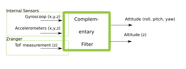
Complementary Filtering
Kalman Filtering
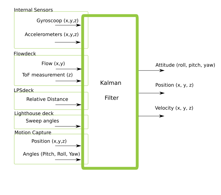
Extended Kalman Filtering
Fight Control Algorithms
Supported Controller
The control system code used in ESP-Drone is from Crazyflie, and continues all its algorithms. Please note that ESP-Drone has only tested and tuned the parameters for PID controller. When using other controllers, tune your parameters while ensuring safety.
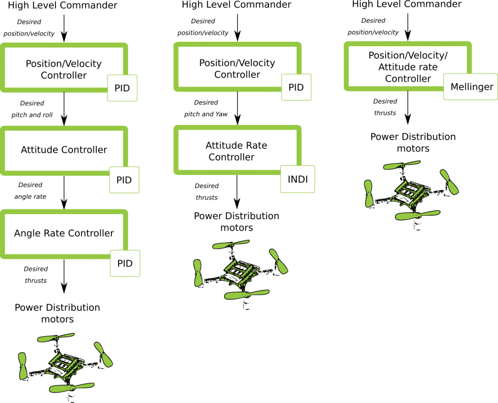
Possible Controller Pathways
For more information, please refer to Out of Control.
In the code, you can modify the input parameters of controllerInit(ControllerType controller) to switch the controller.
Customized controllers can also be added by implementing the following controller interfaces.
static ControllerFcns controllerFunctions[] = {
  {.init = 0, .test = 0, .update = 0, .name = "None"}, // Any
  {.init = controllerPidInit, .test = controllerPidTest, .update = controllerPid, .name = "PID"},
  {.init = controllerMellingerInit, .test = controllerMellingerTest, .update = controllerMellinger, .name = "Mellinger"},
  {.init = controllerINDIInit, .test = controllerINDITest, .update = controllerINDI, .name = "INDI"},
};
PID Controller
How the PID controller works
The PID controller (proportional-integral-derivative controller), consists of a proportional unit, an integral unit, and a derivative unit, corresponding to the current error, past cumulative error and future error, respectively, and then controls the system based on the error and the error rate of change. The PID controller is considered to be the most suitable controller because of its negative feedback correction. By adjusting the PID controller’s three parameters, you can adjust the speed of the system’s response to the error, the degree of the controller’s overswing and shake, so that the system can reach the optimal state.
This drone system has three control dimensions: pitch, roll, and yaw, so it is necessary to design a PID controller with a closed loop as shown in the figure below.
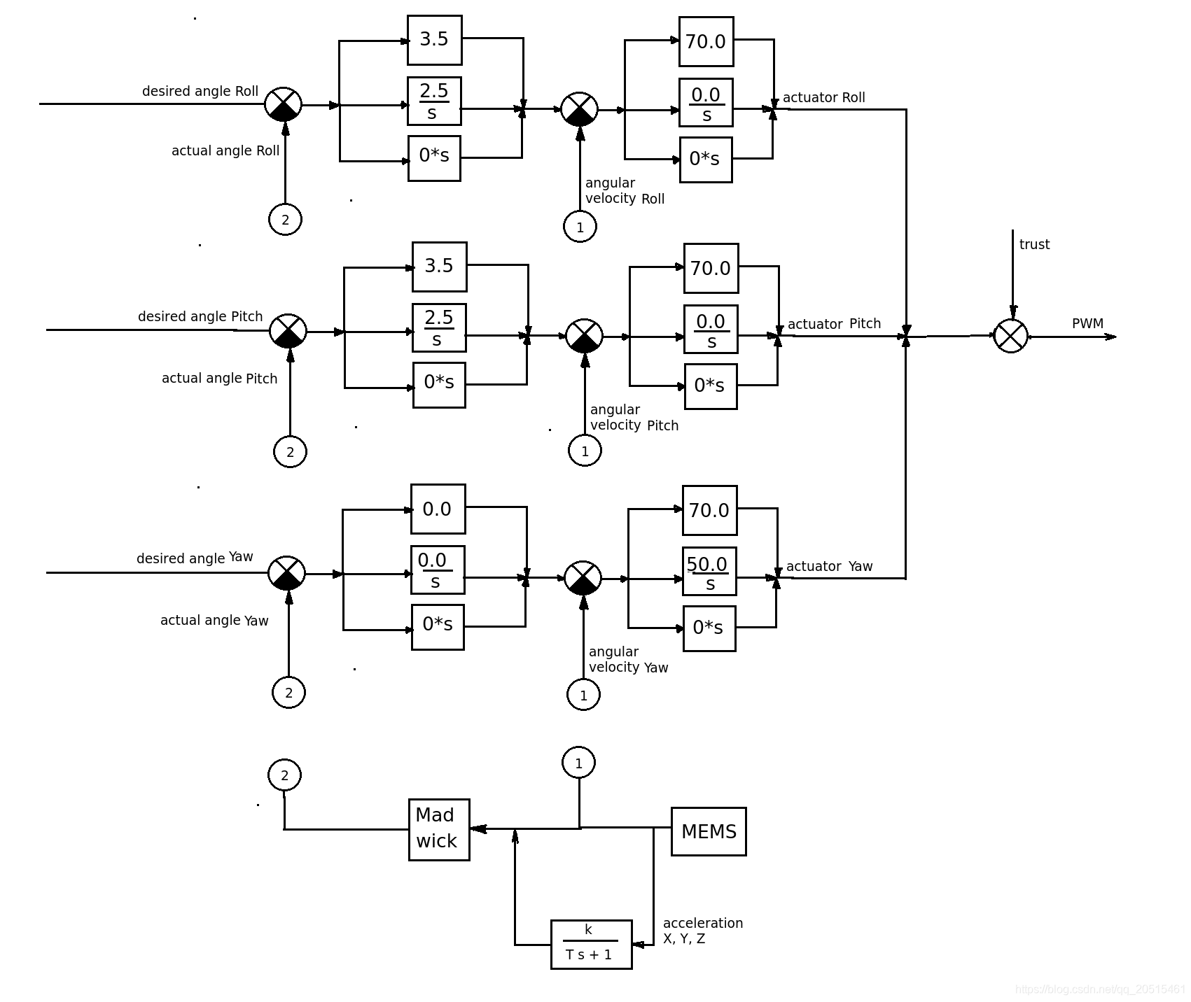
Crazyflie Control System
For each control dimension, a string-level PID controller is provided, consisting of a Rate controller and an Attitude controller. Rate controller is used to control the speed of angle correction based on the input of angular velocity. Attitude controller is used to control the drone to fly at a target angle based on the input of fitting angles. The two controllers can work together at various frequencies. Of course, you can also choose to use only one single-level PID controller, where pitch and roll control dimensions are controlled by Attitude by default, and yaw controlled by Rate.
You can modify the parameters in crtp_commander_rpyt.c:
static RPYType stabilizationModeRoll  = ANGLE; // Current stabilization type of roll (rate or angle)
static RPYType stabilizationModePitch = ANGLE; // Current stabilization type of pitch (rate or angle)
static RPYType stabilizationModeYaw   = RATE;  // Current stabilization type of yaw (rate or angle)
Implementation Code
void controllerPid(control_t *control, setpoint_t *setpoint,
                                         const sensorData_t *sensors,
                                         const state_t *state,
                                         const uint32_t tick)
{
  if (RATE_DO_EXECUTE(ATTITUDE_RATE, tick)) { // This macro controls PID calculation frequency based on the interrupts triggered by MPU6050
    // Rate-controled YAW is moving YAW angle setpoint
    if (setpoint->mode.yaw == modeVelocity) {                                                    //rate mode, correct yaw
       attitudeDesired.yaw += setpoint->attitudeRate.yaw * ATTITUDE_UPDATE_DT;
      while (attitudeDesired.yaw > 180.0f)
        attitudeDesired.yaw -= 360.0f;
      while (attitudeDesired.yaw < -180.0f)
        attitudeDesired.yaw += 360.0f;
    } else {                                                                                                               //attitude mode
      attitudeDesired.yaw = setpoint->attitude.yaw;
    }
  }

  if (RATE_DO_EXECUTE(POSITION_RATE, tick)) {                                               //Position control
    positionController(&actuatorThrust, &attitudeDesired, setpoint, state);
  }

  if (RATE_DO_EXECUTE(ATTITUDE_RATE, tick)) {
    // Switch between manual and automatic position control
    if (setpoint->mode.z == modeDisable) {
      actuatorThrust = setpoint->thrust;
    }
    if (setpoint->mode.x == modeDisable || setpoint->mode.y == modeDisable) {
      attitudeDesired.roll = setpoint->attitude.roll;
      attitudeDesired.pitch = setpoint->attitude.pitch;
    }

    attitudeControllerCorrectAttitudePID(state->attitude.roll, state->attitude.pitch, state->attitude.yaw,
                                attitudeDesired.roll, attitudeDesired.pitch, attitudeDesired.yaw,
                                &rateDesired.roll, &rateDesired.pitch, &rateDesired.yaw);

    // For roll and pitch, if velocity mode, overwrite rateDesired with the setpoint
    // value. Also reset the PID to avoid error buildup, which can lead to unstable
    // behavior if level mode is engaged later
    if (setpoint->mode.roll == modeVelocity) {
      rateDesired.roll = setpoint->attitudeRate.roll;
      attitudeControllerResetRollAttitudePID();
    }
    if (setpoint->mode.pitch == modeVelocity) {
      rateDesired.pitch = setpoint->attitudeRate.pitch;
      attitudeControllerResetPitchAttitudePID();
    }

    // TODO: Investigate possibility to subtract gyro drift.
    attitudeControllerCorrectRatePID(sensors->gyro.x, -sensors->gyro.y, sensors->gyro.z,
                             rateDesired.roll, rateDesired.pitch, rateDesired.yaw);

    attitudeControllerGetActuatorOutput(&control->roll,
                                        &control->pitch,
                                        &control->yaw);

    control->yaw = -control->yaw;
  }

  if (tiltCompensationEnabled)
  {
    control->thrust = actuatorThrust / sensfusion6GetInvThrustCompensationForTilt();
  }
  else
  {
    control->thrust = actuatorThrust;
  }

  if (control->thrust == 0)
  {
    control->thrust = 0;
    control->roll = 0;
    control->pitch = 0;
    control->yaw = 0;

    attitudeControllerResetAllPID();
    positionControllerResetAllPID();

    // Reset the calculated YAW angle for rate control
    attitudeDesired.yaw = state->attitude.yaw;
  }
}
Mellinger Controller
Mellinger controller is an all-in-one controller that directly calculates the required thrust allocated to all motors, based on the target position and the speed vector on the target position.
For your reference: Minimum snap trajectory generation and control for quadrotors.
INDI Controller
An INDI controller is a controller that immediately processes angle rates to determine data reliability. This controller can be used together with a traditional PID controller, which provides a faster angle processing than a string-level PID controller.
For your reference: Adaptive Incremental Nonlinear Dynamic Inversion for Attitude Control of Micro Air Vehicles.
PID Parameter Tuning
Crazyflie Rate PID is tuned as follows:
Adjust
Ratemode first: setrollType,pitchType, andyawTypetoRATE;Adjust
ATTITUDEmode: set theKP,KI, andKDofroll,pitch, andyawto0.0, and only remain the parameters ofRateunchanged.Adjust
RATEmode: set theKI,KDofroll,pitchandyawto0.0. Set theKPfirst.Burn the code and start the
KPadjustment online using the param function of cfclient.Note that the modified parameters using cfclient will not be saved when power down;
During PID tuning, shake (over-tuning) may happen, please be careful.
Hold the drone to make sure it can only roll around
pitchaxis. Gradually increase theKPofpitch, till the drone starts shaking back and forth.If the drone shakes intensely, slightly lower
KP, generally 5%-10% lower than the shake’s critical point.Tune the
rollandyawin the same way.Adjust
KIto eliminate steady-state errors. If only with proportional adjustment, but without this parameter, the drone may swing up and down at Position 0 due to the interference such as gravity. Set the initial value ofKIto 50% ofKP.When the
KIincreases to certain value, the drone starts shaking. But compared with the shake caused byKI, that caused byKPis more low-frequency. Keep in mind the point when the drone starts shaking, and mark thisKIas the critical point. The finalKIshould be 5%-10% lower than this critical point.Tune the
rollandyawin the same way.In general, the value of
KIshould be over 80% of theKP.
Rate PID parameter tuning is done now.
Let’s start the tuning of Attitude PID
First ensure that
Rate PIDtuning is completed.Adjust
rollType,pitchType, andyawTypetoANGLE, i.e. the drone is in attitude mode now.Set the
KIandKDofrollandpitchto0.0, and then set theKP,KI, andKDofYawto0.0.Burn the code and start the
KPtuning online using the param function of cfclient.Set the
KPofrollandpitchto3.5. Check for any existing instability, such as shakes. Keep increasing the KP until the limit is reached;If the
KPalready is causing drone instability, or the value is over4, please lower theKPandKIofRATEmode by 5% ~ 10%. By such way, we have more freedom to tune the Attitude mode.If you still need to adjust the KI, please slowly increase KI again. If some low-frequency shakes occur, it indicates that your drone is in an unstable state.