Hardware Reference
Supported Hardware
Supported Hardware List
Development Board |
Main Components |
Notes |
|---|---|---|
ESP32-S2-Drone V1.2 |
ESP32-S2-WROVER + MPU6050 |
All in one |
ESPlane-V2-S2 |
ESP32-S2-WROVER + MPU6050 |
Four feet should be installed |
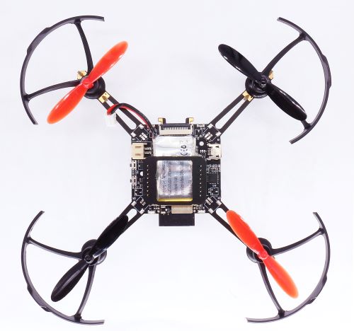
ESPlane-FC-V1 |
ESP32-WROOM-32D + MPU6050 |
A drone frame should be installed |
Configure Target Hardware
Code in
esp_dronerepository supports a wide variety of hardware, which can be changed throughmenuconfig.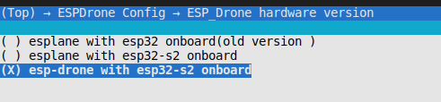
By default, when set
set-targetasesp32s2, target hardware will be changed toESP32_S2_Drone_V1_2automatically.By default, when set
set-targetasesp32, target hardware will be changed toESPlane_FC_V1automatically.
Notes
ESPlane-FC-V1 is an old version hardware.
To use ESP-Drone new version code on ESPlane-FC-V1, please connect GPIO14 of ESP32-WROOM-32D to INT pin of MPU6050 by a jumper.
To avoid flash voltage switching triggered by IO12 when ESPlane-FC-V1 is powered on, please fix the flash voltage to 3.3 V by running
espefuse.pyscriptespefuse.py --port /dev/ttyUSB0 set_flash_voltage 3.3Vnote * Only the first device attaching to the bus can use CS0 pin.
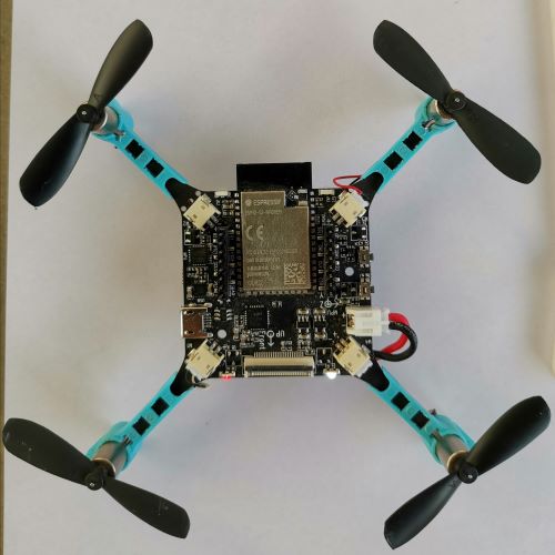
ESP32-S2-Drone V1.2
ESP32-S2-Drone V1.2 Overview
Main Board Schematic:SCH_Mainboard_ESP32_S2_Drone_V1_2
Main Board PCB:PCB_Mainboard_ESP32_S2_Drone_V1_2
Basic Component
Basic Component List
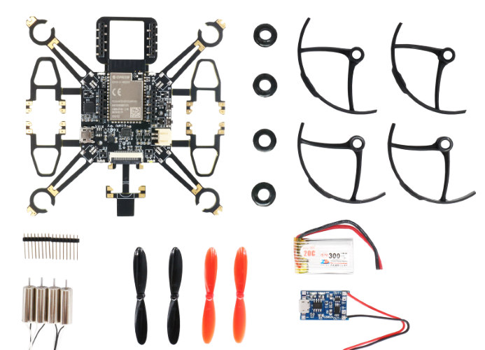
Component List for ESP32-S2-Drone V1.2
Basic Component List |
Number |
Notes |
|---|---|---|
Main board |
1 |
ESP32-S2-WROVER + MPU6050 |
716 motor |
4 |
Optional: 720 motor |
716 motor rubber ring |
4 |
|
46mm propeller A |
2 |
Optional: 55mm propeller |
46mm propeller B |
2 |
|
300mAh 1s LiPo battery |
1 |
Optional: 350mAh |
1s LiPo battery charging panel |
1 |
|
8-pin 25 mm male pins |
2 |
Note
Set motor type as brushed 720 motor through menuconfig->ESPDrone Config->motors config if you use 720 motor.
Main Controller
Chip |
Module |
Notes |
|---|---|---|
ESP32-S2 |
ESP32-S2-WROVER |
4 MB flash, 2 MB PSRAM in module |
Sensor
Sensor |
Interface |
Notes |
|---|---|---|
MPU6050 |
I2C0 |
Main board Sensor |
LEDs
Status |
LED |
Action |
|---|---|---|
POWER_ON |
WHITE |
Fully lit |
SENSORS CALIBRATION |
BLUE |
Blinking slowly |
SYSTEM READY |
BLUE |
Blinking |
UDP_RX |
GREEN |
Blinking |
LOW_POWER |
RED |
Fully lit |
Definition of Main Board IO
Pins |
Function |
Notes |
|---|---|---|
GPIO11 |
I2C0_SDA |
Only for MPU6050 |
GPIO10 |
I2C0_SCL |
Only for MPU6050 |
GPIO37 |
SPI_MISO |
MISO |
GPIO35 |
SPI_MOSI |
MOSI |
GPIO36 |
SPI_CLK |
SCLK |
GPIO34 |
SPI_CS0 |
CS0* |
GPIO40 |
I2C1_SDA |
VL53L1X |
GPIO41 |
I2C1_SCL |
VL53L1X |
GPIO12 |
interrupt |
MPU6050 interrupt |
GPIO39 |
BUZ_1 |
BUZZ+ |
GPIO38 |
BUZ_2 |
BUZZ- |
GPIO8 |
LED_RED |
LED_1 |
GPIO9 |
LED_GREEN |
LED_2 |
GPIO7 |
LED_BLUE |
LED_3 |
GPIO5 |
MOT_1 |
|
GPIO6 |
MOT_2 |
|
GPIO3 |
MOT_3 |
|
GPIO4 |
MOT_4 |
|
GPIO2 |
ADC_7_BAT |
VBAT/2 |
GPIO1 |
EXT_IO1 |
Camera Interface
Pins |
Function |
|---|---|
GPIO13 |
CAM_VSYNC |
GPIO14 |
CAM_HREF |
GPIO15 |
CAM_Y9 |
GPIO16 |
CAM_XCLK |
GPIO17 |
CAM_Y8 |
GPIO18 |
CAM_RESET |
GPIO19 |
CAM_Y7 |
GPIO20 |
CAM_PCLK |
GPIO21 |
CAM_Y6 |
GPIO33 |
CAM_Y2 |
GPIO45 |
CAM_Y4 |
GPIO46 |
CAM_Y3 |
Extension Components
Extension Board |
Main Sensor |
Function |
Interfaces |
Mount Location |
|---|---|---|---|---|
Position-hold module |
PMW3901 + VL53L1X |
Indoor position-hold flight |
SPI + I2C |
Mount at bottom, facing to the ground. |
Pressure module |
MS5611 pressure module |
Height-hold flight |
I2C or MPU6050 slave |
Mount at the top or at the bottom |
Compass module |
HMC5883 compass |
Advanced flight mode, such as head-free mode |
I2C or MPU6050 slave |
Mount at the top or at the bottom |
Definition of Extension Board IO
Left Pins |
IO |
Right pins |
IO |
|---|---|---|---|
SPI_CS0 |
GPIO34 |
VDD_33 |
IO |
SPI_MOSI |
GPIO35 |
I2C0_SDA |
GPIO11 |
SPI_CLK |
GPIO36 |
I2C0_SCL |
GPIO10 |
SPI_MISO |
GPIO37 |
GND |
|
GND |
AUX_SCL |
||
I2C1_SDA |
GPIO40 |
AUX_SDA |
|
I2C1_SCL |
GPIO41 |
BUZ_2 |
GPIO38 |
EXT_IO1 |
GPIO1 |
BUZ_1 |
GPIO39 |
ESPlane-V2-S2
ESPlane-V2-S2 Overview
Main Board Schematic:SCH_ESPlane_V2_S2
Main Board PCB:PCB_ESPlane_V2_S2
ESPlane-FC-V1
esplane_fc_v1
Main Board Schematic:Schematic_ESPlane_FC_V1
Main Board PCB:PCB_ESPlane_FC_V1
Basic Component
Basic Component List
Basic Component List |
Number |
Notes |
|---|---|---|
Main board |
1 |
ESP32-WROOM-32D + MPU6050 |
Drone frame |
1 |
|
46 mm propeller A |
2 |
|
46 mm propeller B |
2 |
|
300 mAh 1s LiPo battery |
1 |
|
1s LiPo battery charging panel |
1 |
Sensor
Sensor |
Interface |
Notes |
|---|---|---|
MPU6050 |
I2C0 |
Must |
LEDs
#define LINK_LED         LED_BLUE
//#define CHG_LED        LED_RED
#define LOWBAT_LED       LED_RED
//#define LINK_DOWN_LED  LED_BLUE
#define SYS_LED          LED_GREEN
#define ERR_LED1         LED_RED
#define ERR_LED2         LED_RED
Status |
LED |
Action |
|---|---|---|
SENSORS READY |
BLUE |
Fully lit |
SYSTEM READY |
BLUE |
Fully lit |
UDP_RX |
GREEN |
Blinking |
Definition of Main Board IO
Pins |
Function |
Notes |
|---|---|---|
GPIO21 |
SDA |
I2C0 data |
GPIO22 |
SCL |
I2C0 clock |
GPIO14 |
SRV_2 |
MPU6050 interrupt |
GPIO16 |
RX2 |
|
GPIO17 |
TX2 |
|
GPIO27 |
SRV_3 |
BUZZ+ |
GPIO26 |
SRV_4 |
BUZZ- |
GPIO23 |
LED_RED |
LED_1 |
GPIO5 |
LED_GREEN |
LED_2 |
GPIO18 |
LED_BLUE |
LED_3 |
GPIO4 |
MOT_1 |
|
GPIO33 |
MOT_2 |
|
GPIO32 |
MOT_3 |
|
GPIO25 |
MOT_4 |
|
TXD0 |
||
RXD0 |
||
GPIO35 |
ADC_7_BAT |
VBAT/2 |
Components of Extension Board
ESPlane + PMW3901 Pins Allocation
Pins |
Function |
Notes |
|---|---|---|
GPIO21 |
SDA |
I2C0 data |
GPIO22 |
SCL |
I2C0 clock |
GPIO12 |
MISO/SRV_1 |
HSPI |
GPIO13 |
MOSI |
HSPI |
GPIO14 |
SCLK/SRV_2 |
HSPI |
GPIO15 |
CS0* |
HSPI |
GPIO16 |
RX2 |
|
GPIO17 |
TX2 |
|
GPIO19 |
interrupt |
MPU6050 interrupt |
GPIO27 |
SRV_3 |
BUZZ+ |
GPIO26 |
SRV_4 |
BUZZ- |
GPIO23 |
LED_RED |
LED_1 |
GPIO5 |
LED_GREEN |
LED_2 |
GPIO18 |
LED_BLUE |
LED_3 |
GPIO4 |
MOT_1 |
|
GPIO33 |
MOT_2 |
|
GPIO32 |
MOT_3 |
|
GPIO25 |
MOT_4 |
|
TXD0 |
||
RXD0 |
||
GPIO35 |
ADC_7_BAT |
VBAT/2 |