Downloading Guide
This Guide demonstrates how to download AT firmware and flash it into an ESP32-WROOM-32 device by taking ESP32-WROOM-32 as an example. The Guide is also applicable to other ESP32 modules.
Before you start, please make sure you have already connected your hardware. For more details, see Hardware Connection.
For different series of modules, the commands supported by AT firmware are different. Please refer to ESP-AT Firmware Differences for more details.
Download AT Firmware
To download AT firmware to your computer, please do as follows:
Navigate to AT Binary Lists
Find the firmware for your device
Click the link to download it
Here, we download ESP32-WROOM-32-AT-V3.2.0.0 for ESP32-WROOM-32. The list below describes the structure of this firmware and what each bin file contains. Other AT firmware has similar structure and bin files.
.
├── at_customize.bin                 // secondary partition table
├── bootloader                       // bootloader
│   └── bootloader.bin
├── customized_partitions            // AT customized binaries
      ├── mfg_nvs.csv                  // raw data of manufacturing nvs partition
│   └── mfg_nvs.bin                  // manufacturing nvs partition binary
├── download.config                  // configuration of downloading
├── esp-at.bin                       // AT application binary
├── esp-at.elf
├── esp-at.map
├── factory                          // A combined bin for factory downloading
│   └── factory_XXX.bin
├── flasher_args.json                // flasher arguments
├── ota_data_initial.bin             // ota data parameters
├── partition_table                  // primary partition table
│   └── partition-table.bin
└── sdkconfig                        // compilation configuration for AT firmware
The file download.config contains the configuration to flash the firmware into multiple addresses:
--flash_mode dio --flash_freq 40m --flash_size 4MB
0x1000 bootloader/bootloader.bin
0x8000 partition_table/partition-table.bin
0x10000 ota_data_initial.bin
0x20000 at_customize.bin
0x21000 customized_partitions/mfg_nvs.bin
0x100000 esp-at.bin
--flash_mode diomeans the firmware is compiled with flash DIO mode.--flash_freq 40mmeans the firmware’s flash frequency is 40 MHz.--flash_size 4MBmeans the firmware is using flash size 4 MB.0x10000 ota_data_initial.binmeans downloadingota_data_initial.bininto the address0x10000.
Flash AT Firmware into Your Device
Follow the instructions below for your operating system.
Windows
Before starting to flash, you need to download Flash Download Tool for Windows. You can refer to the Flash Download Tool User Guide for instructions.
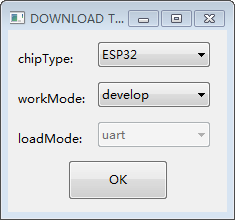
Open the ESP32 Flash Download Tool.
Select chipType. (Here, we select
ESP32.)Select a workMode according to your need. (Here, we select
Developer Mode.)Select a loadMode according to your need. (Here, we select
uart.)
Firmware Download Configurations
Flash AT firmware into your device. You can select either of the two ways below.
To download one combined factory bin (namely,
factory_XXX.binin thebuild/factorydirectory) to address0x0, select “DoNotChgBin” to use the default configuration of the factory bin.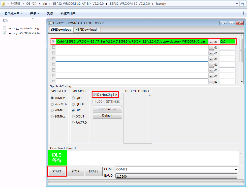
Download to One Address (click to enlarge)
To download multiple bins separately to different addresses, set up the configurations according to the file
download.configand do NOT select “DoNotChgBin”.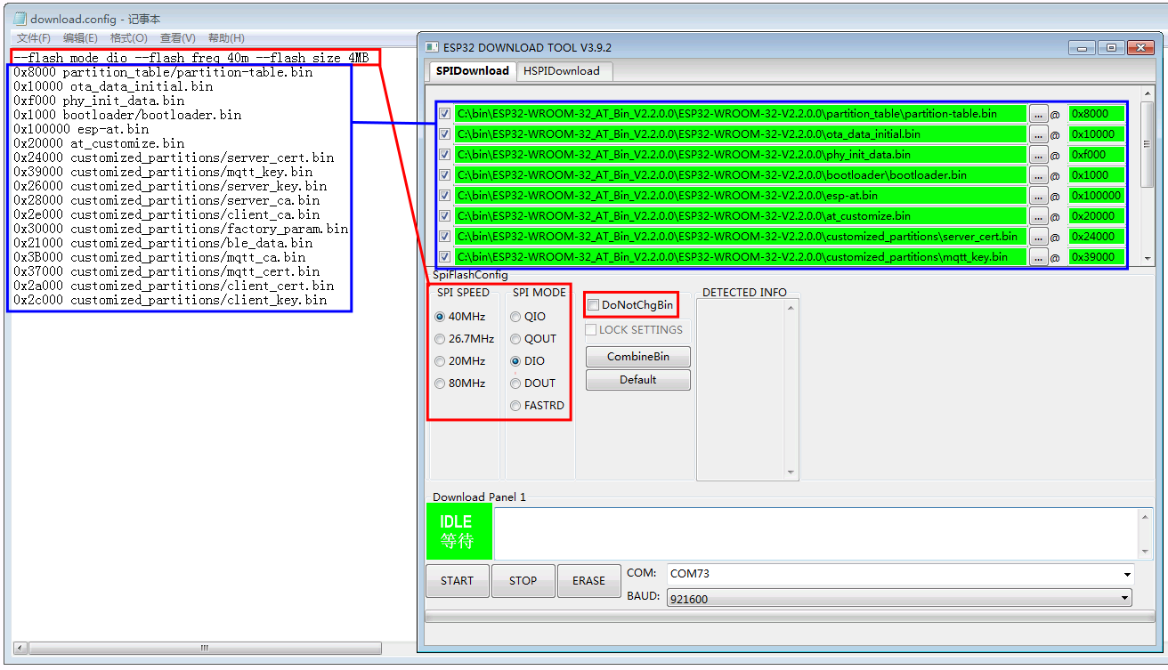
Download to Multiple Addresses (click to enlarge)
In case of flashing issues, please verify what the COM port number of download interface of the ESP32 board is and select it from “COM:” dropdown list. If you do not know the port number, you can refer to Check port on Windows for details.
When you finish flashing, please Check Whether AT Works.
Linux or macOS
Before you start to flash, you need to install esptool.py.
You can select either of the two ways below to flash AT firmware into your device.
To download the bins separately into multiple addresses, enter the following command and replace
PORTNAMEanddownload.config:esptool.py --chip auto --port PORTNAME --baud 115200 --before default_reset --after hard_reset write_flash -z download.config
Replace
PORTNAMEwith your port name. If you do not know it, you can refer to Check port on Linux and macOS for details.Replace
download.configwith the content inside the file.Below is the example command for ESP32-WROOM-32.
esptool.py --chip auto --port /dev/tty.usbserial-0001 --baud 115200 --before default_reset --after hard_reset write_flash -z --flash_mode dio --flash_freq 40m --flash_size 4MB 0x8000 partition_table/partition-table.bin 0x10000 ota_data_initial.bin 0x1000 bootloader/bootloader.bin 0x100000 esp-at.bin 0x20000 at_customize.bin 0x21000 customized_partitions/mfg_nvs.bin
To download the bins together to one address, enter the following command and replace
PORTNAMEandFILEDIRECTORY:esptool.py --chip auto --port PORTNAME --baud 115200 --before default_reset --after hard_reset write_flash -z --flash_mode dio --flash_freq 40m --flash_size 4MB 0x0 FILEDIRECTORY
Replace
PORTNAMEwith your port name. If you do not know it, you can refer to Check port on Linux and macOS for details.Replace
FILEDIRECTORYwith the file directory you would flash to the address0x0. It is normally factory/XXX.bin.Below is the example command for ESP32-WROOM-32.
esptool.py --chip auto --port /dev/tty.usbserial-0001 --baud 115200 --before default_reset --after hard_reset write_flash -z --flash_mode dio --flash_freq 40m --flash_size 4MB 0x0 factory/factory_WROOM-32.bin
When you finish flashing, please Check Whether AT Works.
Check Whether AT Works
To check whether AT works, do as follows:
Open a serial port tool, such as SecureCRT;
Select the Port attached to “AT command/response” line (see Hardware Connection for details);
Set Baudrate to 115200;
Set Data Bits to 8;
Set Parity to None;
Set Stop Bits to 1;
Set Flow Type to None;
Enter the command “AT+GMR” with a new line (CR LF).
If the response is OK as shown below, AT works.
AT+GMR
AT version:3.2.0.0(s-ec2dec2 - ESP32 - Jul 28 2023 07:05:28)
SDK version:v5.0.2-376-g24b9d38a24-dirty
compile time(6118fc22):Jul 28 2023 09:47:28
Bin version:v3.2.0.0(WROOM-32)

OK
Otherwise, you need to check your ESP32 startup log in one of the following ways:
Method 1:
Open a serial port tool, such as SecureCRT;
Select the port attached to the “Download/Log output” line. For more information on this line, see Hardware Connection.
Set Baudrate to 115200;
Set Data Bits to 8;
Set Parity to None;
Set Stop Bits to 1;
Set Flow Type to None;
Press the RST key of the board directly. If it is like the log below, it means that ESP-AT firmware have been initialized correctly.
Method 2:
Open two serial port tools, such as SecureCRT;
In one serial port tool, select the port attached to the “AT command/response” line. In the other tool, select the port attached to the “Download/Log output” line. For more information on these lines, see Hardware Connection.
Set Baudrate to 115200;
Set Data Bits to 8;
Set Parity to None;
Set Stop Bits to 1;
Set Flow Type to None;
Enter the command AT+RST with a new line (CR LF) to the “AT command/response” line. If the serial log from the “Download/Output log” line is like the log below, it means that ESP-AT firmware have been initialized correctly.
ESP32 startup log:
rst:0x1 (POWERON_RESET),boot:0x13 (SPI_FAST_FLASH_BOOT)
configsip: 0, SPIWP:0xee
clk_drv:0x00,q_drv:0x00,d_drv:0x00,cs0_drv:0x00,hd_drv:0x00,wp_drv:0x00
mode:DIO, clock div:2
load:0x3fff0030,len:5884
ho 0 tail 12 room 4
load:0x40078000,len:15844
load:0x40080400,len:3560
entry 0x40080604
I (29) boot: ESP-IDF v5.0-541-g885e501d99-dirty 2nd stage bootloader
I (29) boot: compile time 08:40:13
I (29) boot: chip revision: v1.0
I (34) boot.esp32: SPI Speed      : 40MHz
I (38) boot.esp32: SPI Mode       : DIO
I (43) boot.esp32: SPI Flash Size : 4MB
I (47) boot: Enabling RNG early entropy source...
I (53) boot: Partition Table:
I (56) boot: ## Label            Usage          Type ST Offset   Length
I (64) boot:  0 phy_init         RF data          01 01 0000f000 00001000
I (71) boot:  1 otadata          OTA data         01 00 00010000 00002000
I (78) boot:  2 nvs              WiFi data        01 02 00012000 0000e000
I (86) boot:  3 at_customize     unknown          40 00 00020000 000e0000
I (93) boot:  4 ota_0            OTA app          00 10 00100000 00180000
I (101) boot:  5 ota_1            OTA app          00 11 00280000 00180000
I (108) boot: End of partition table
I (113) esp_image: segment 0: paddr=00100020 vaddr=3f400020 size=1a854h (108628) map
I (161) esp_image: segment 1: paddr=0011a87c vaddr=3ff80063 size=00008h (     8) load
I (161) esp_image: segment 2: paddr=0011a88c vaddr=3ffbdb60 size=04d5ch ( 19804) load
I (174) esp_image: segment 3: paddr=0011f5f0 vaddr=40080000 size=00a28h (  2600) load
I (176) esp_image: segment 4: paddr=00120020 vaddr=400d0020 size=11f5c0h (1177024) map
I (609) esp_image: segment 5: paddr=0023f5e8 vaddr=40080a28 size=1e948h (125256) load
I (660) esp_image: segment 6: paddr=0025df38 vaddr=400c0000 size=00064h (   100) load
I (676) boot: Loaded app from partition at offset 0x100000
I (676) boot: Disabling RNG early entropy source...
no external 32k oscillator, disable it now.
at param mode: 1
AT cmd port:uart1 tx:17 rx:16 cts:15 rts:14 baudrate:115200
module_name: WROOM-32
max tx power=78, ret=0
2.5.0