ESP-BLE-MESH
Bluetooth® mesh networking enables many-to-many (m:m) device communications and is optimized for creating large-scale device networks.
Devices may relay data to other devices not in direct radio range of the originating device. In this way, mesh networks can span very large physical areas and contain large numbers of devices. It is ideally suited for building automation, sensor networks, and other IoT solutions where tens, hundreds, or thousands of devices need to reliably and securely communicate with one another.
Bluetooth mesh is not a wireless communications technology, but a networking technology. This technology is dependent upon Bluetooth Low Energy (BLE) - a wireless communications protocol stack.
Built on top of Zephyr Bluetooth Mesh stack, the ESP-BLE-MESH implementation supports device provisioning and node control. It also supports such node features as Proxy, Relay, Low power and Friend.
Please see the ESP-BLE-MESH Architecture for information about the implementation of ESP-BLE-MESH architecture and ESP-BLE-MESH API Reference for information about respective API.
ESP-BLE-MESH is implemented and certified based on the latest Mesh Profile v1.0.1, users can refer here for the certification details of ESP-BLE-MESH.
Note
If you are looking for Wi-Fi based implementation of mesh for ESP32-C3, please check another product by Espressif called ESP-MESH. For more information and documentation see ESP-MESH.
Getting Started with ESP-BLE-MESH
This section is intended to help you get started with ESP-BLE-MESH for the hardware based on the ESP32-C3 chip by Espressif.
We are going to demonstrate process of setting and operation of a small ESP-BLE-MESH network of three nodes. This process will cover device provisioning and node configuration, and then sending on/off commands to Generic OnOff Server Models on specific nodes.
If you are new to ESP-IDF, please first set up development environment, compile , flash and run example application following top level ESP-IDF Get Started documentation.
What You Need
Hardware:
Three ESP32-C3 boards, see options.
USB cables to connect the boards.
Computer configured with ESP-IDF.
Mobile phone or tablet running Android or iOS.
Software:
Example application bluetooth/esp_ble_mesh/ble_mesh_node/onoff_server code to load to the ESP32-C3 boards.
Mobile App: nRF Mesh for Android or iOS. Optionally you can use some other Apps:
EspBleMesh Android App
Silicon Labs Android or iOS App
Installation Step by Step
This is a detailed roadmap to walk you through the installation process.
Step 1. Check Hardware
Both ESP32-DevKitC and ESP-WROVER-KIT development boards are supported for ESP-BLE-MESH implementation. You can choose particular board through menuconfig: idf.py menuconfig > Example Configuration > Board selection for ESP-BLE-MESH
Note
If you plan to use ESP32-DevKitC, connect a RGB LED to GPIO pins 25, 26 and 27.
Step 2. Configure Software
Enter the bluetooth/esp_ble_mesh/ble_mesh_node/onoff_server example directory, run idf.py menuconfig to select your board and then run idf.py build to compile the example.
Step 3. Upload Application to Nodes
After the bluetooth/esp_ble_mesh/ble_mesh_node/onoff_server example is compiled successfully, users can run idf.py flash to upload the same generated binary files into each of the three development boards.
Once boards are powered on, the RGB LED on each board should turn GREEN.
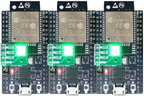
ESP-BLE-MESH Devices Power On
Step 4. Provision Nodes
In this section, we will use the nRF Mesh Android App to demonstrate how to provision an unprovisioned device. Users can also get its iOS version from the App Store.
4.1 Scanner
The Scanner is App’s functionality to search for unprovisioned devices in range. Open the App, press Scanner at the bottom and the search will start. After a short while we should see three unprovisioned devices displayed.
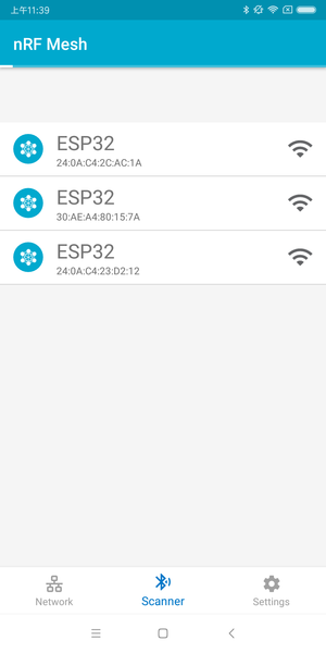
nRF Mesh - Scanner
4.2 Identify
Users can select any unprovisioned device, then the App will try to set up a connection with the selected device. After the BLE connection is established successfully (sometimes users need to try multiple times to get connected), and proper ESP-BLE-MESH GATT Service is discovered, users can see the IDENTIFY interface button on the screen. The IDENTIFY operation can be used to tell users which device is going to be provisioned.
Note
The IDENTIFY operation also needs some cooperation on the device side, then users can see which device is in the provisioning process. Currently when pressing the IDENTIFY interface button, no signs can been seen from the device except from the log on the serial monitor.
After the IDENTIFY interface button is pressed, users can see the PROVISION interface button.
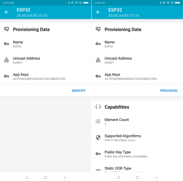
nRF Mesh - IDENTIFY - PROVISION
4.3 Provision
Then, the App will try to provision the unprovisioned device. When the device is provisioned successfully, the RGB LED on the board will turn off, and the App will implement the following procedures:
Disconnect with the node
Try to reconnect with the node
Connect successfully and discover ESP-BLE-MESH GATT Service
Get Composition Data of the node and add AppKey to it
When all the procedures are finished, the node is configured properly. And after pressing OK, users can see that unicast address is assigned, and Composition Data of the node is decoded successfully.
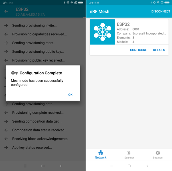
nRF Mesh - Configuration Complete
Sometimes in procedure 2, the App may fail to reconnect with the node. In this case, after pressing OK, users can see that only unicast address of the node has been assigned, but no Composition Data has been got. Then users need to press CONNECT on the top right, and the previously provisioned node will be displayed on the screen, and users need to choose it and try to connect with the node.
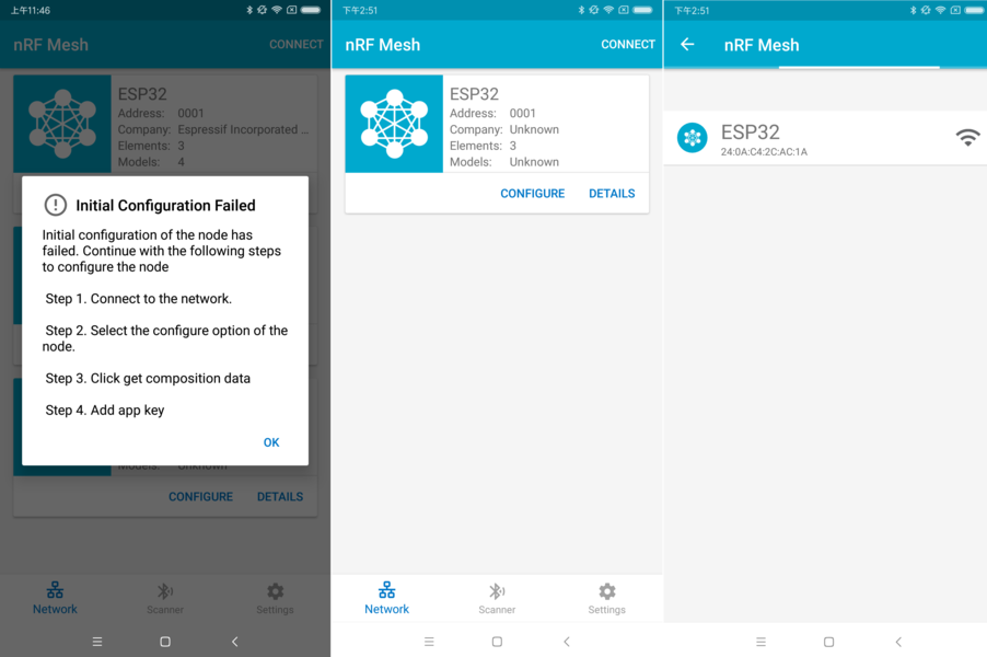
nRF Mesh - Initial Configuration Failed
After connecting successfully, the App will show the interface buttons which can be used to get Composition Data and add AppKey.
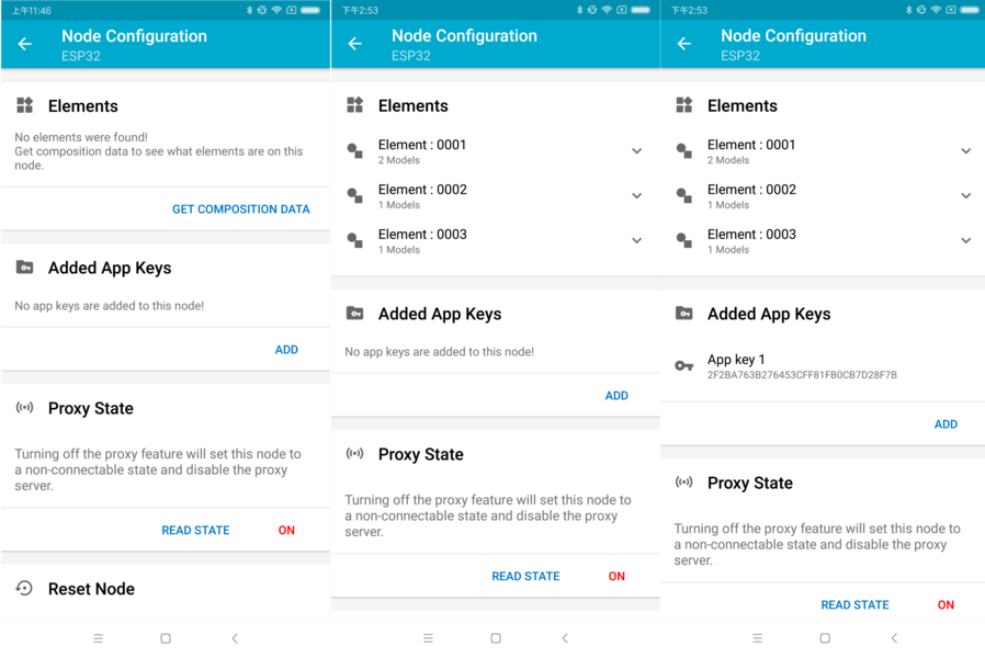
nRF Mesh - Reconnect - Initial Configuration
If the device is the second or the third one which has been provisioned by the App, and after pressing CONNECT, users can see two or three nodes on the screen. In this situation, users can choose any device to connect with, once succeed then go back to the main screen to choose the node which needs to be configured.
Here an example of three devices listed.
The left picture shows that the third device is provisioned successfully, but the App failed to connect with it. When it tries to reconnect with the third node, three nodes are displayed on the App.
The right picture shows that after connecting with any node successfully, the App displays the information of the three nodes. Users can see that the App has got the Composition Data of the first and the second nodes, but for the third one, only the unicast address has been assigned to it while the Composition Data is unknown.
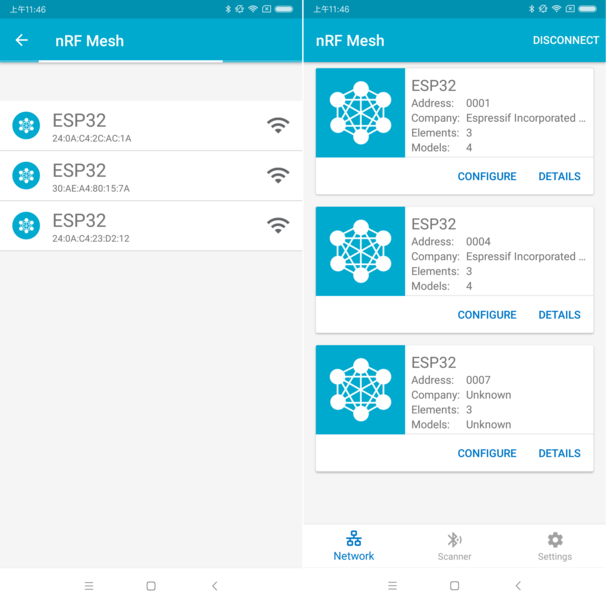
nRF Mesh - Reconnect - Three Nodes
4.4 Configuration
When provisioning and initial configuration are finished, users can start to configure the node, such as binding AppKey with each model with the elements, setting publication information to it, etc.
Example below shows how to bind AppKey with Generic OnOff Server Model within the Primary Element.
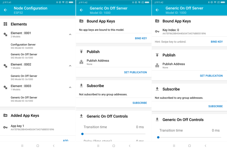
nRF Mesh - Model Bind AppKey
Note
No need to bind AppKey with the Configuration Server Model, since it only uses the DevKey to encrypt messages in the Upper Transport Layer.
Step 5. Operate Network
After all the Generic OnOff Server Models within the three elements are bound with proper AppKey, users can use the App to turn on/off the RGB LED.
In the bluetooth/esp_ble_mesh/ble_mesh_node/onoff_server example, the first Generic OnOff Server Model is used to control the RED color, the second one is used to control the GREEN color and the third one is used to control the BLUE color.
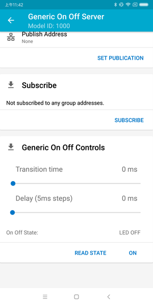
nRF Mesh - Generic OnOff Control
The following screenshot shows different board with different color on.
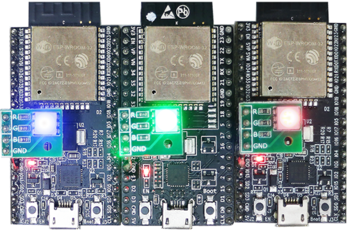
Three ESP-BLE-MESH Nodes On
Note
For nRF Mesh iOS App [version 1.0.4], when the node contains more than one element, the App is not behaving correctly. If users try to turn on/off the second or the third Generic OnOff Server Model, the message sent by the App is destinated to the first Generic OnOff Server Model within the Primary Element.
ESP-BLE-MESH Examples
ESP-BLE-MESH Node OnOff Server - shows the use of ESP-BLE-MESH as a node having a Configuration Server model and a Generic OnOff Server model. A ESP-BLE-MESH Provisioner can then provision the unprovisioned device and control a RGB LED representing on/off state, see example code .
ESP-BLE-MESH Node OnOff Client - shows how a Generic OnOff Client model works within a node. The node has a Configuration Server model and a Generic OnOff Client model, see example code .
ESP-BLE-MESH Provisioner - shows how a device can act as an ESP-BLE-MESH Provisioner to provision devices. The Provisioner has a Configuration Server model, a Configuration Client model and a Generic OnOff Client model, see example code .
ESP-BLE-MESH Fast Provisioning - Client and Server - this example is used for showing how fast provisioning can be used in order to create a mesh network. It takes no more than 60 seconds to provision 100 devices, see example client code and example server code .
ESP-BLE-MESH and Wi-Fi Coexistence - an example that demonstrates the Wi-Fi and Bluetooth (BLE/BR/EDR) coexistence feature of ESP32-C3. Simply put, users can use the Wi-Fi while operating Bluetooth, see example code .
ESP-BLE-MESH Console - an example that implements BLE Mesh basic features. Within this example a node can be scanned and provisioned by Provisioner and reply to get/set message from Provisioner, see example node code .