ESP-MESH
This guide provides information regarding the ESP-MESH protocol. Please see the MESH API Reference for more information about API usage.
Overview
ESP-MESH is a networking protocol built atop the Wi-Fi protocol. ESP-MESH allows numerous devices (henceforth referred to as nodes) spread over a large physical area (both indoors and outdoors) to be interconnected under a single WLAN (Wireless Local-Area Network). ESP-MESH is self-organizing and self-healing meaning the network can be built and maintained autonomously.
The ESP-MESH guide is split into the following sections:
Introduction
Traditional Wi-Fi Network Architecture
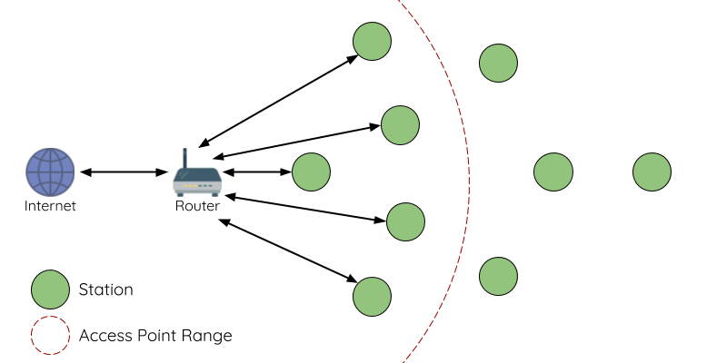
A traditional infrastructure Wi-Fi network is a point-to-multipoint network where a single central node known as the access point (AP) is directly connected to all other nodes known as stations. The AP is responsible for arbitrating and forwarding transmissions between the stations. Some APs also relay transmissions to/from an external IP network via a router. Traditional infrastructure Wi-Fi networks suffer the disadvantage of limited coverage area due to the requirement that every station must be in range to directly connect with the AP. Furthermore, traditional Wi-Fi networks are susceptible to overloading as the maximum number of stations permitted in the network is limited by the capacity of the AP.
ESP-MESH Network Architecture
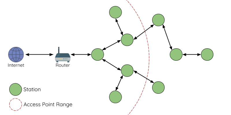
ESP-MESH differs from traditional infrastructure Wi-Fi networks in that nodes are not required to connect to a central node. Instead, nodes are permitted to connect with neighboring nodes. Nodes are mutually responsible for relaying each others transmissions. This allows an ESP-MESH network to have much greater coverage area as nodes can still achieve interconnectivity without needing to be in range of the central node. Likewise, ESP-MESH is also less susceptible to overloading as the number of nodes permitted on the network is no longer limited by a single central node.
ESP-MESH Concepts
Terminology
Term |
Description |
|---|---|
Node |
Any device that is or can be part of an ESP-MESH network |
Root Node |
The top node in the network |
Child Node |
A node X is a child node when it is connected to another node Y where the connection makes node X more distant from the root node than node Y (in terms of number of connections). |
Parent Node |
The converse notion of a child node |
Descendant Node |
Any node reachable by repeated proceeding from parent to child |
Sibling Nodes |
Nodes that share the same parent node |
Connection |
A traditional Wi-Fi association between an AP and a station. A node in ESP-MESH will use its station interface to associate with the softAP interface of another node, thus forming a connection. The connection process includes the authentication and association processes in Wi-Fi. |
Upstream Connection |
The connection from a node to its parent node |
Downstream Connection |
The connection from a node to one of its child nodes |
Wireless Hop |
The portion of the path between source and destination nodes that corresponds to a single wireless connection. A data packet that traverses a single connection is known as single-hop whereas traversing multiple connections is known as multi-hop. |
Subnetwork |
A subnetwork is subdivision of an ESP-MESH network which consists of a node and all of its descendant nodes. Therefore the subnetwork of the root node consists of all nodes in an ESP-MESH network. |
MAC Address |
Media Access Control Address used to uniquely identify each node or router within an ESP-MESH network. |
DS |
Distribution System (External IP Network) |
Tree Topology
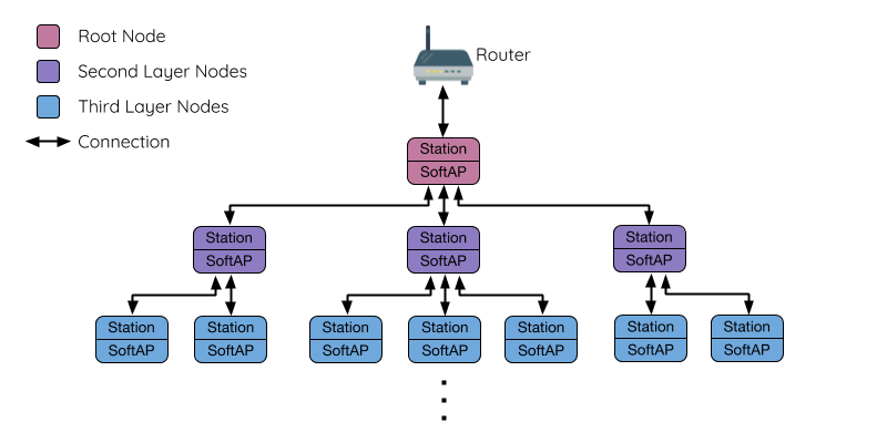
ESP-MESH is built atop the infrastructure Wi-Fi protocol and can be thought of as a networking protocol that combines many individual Wi-Fi networks into a single WLAN. In Wi-Fi, stations are limited to a single connection with an AP (upstream connection) at any time, whilst an AP can be simultaneously connected to multiple stations (downstream connections). However ESP-MESH allows nodes to simultaneously act as a station and an AP. Therefore a node in ESP-MESH can have multiple downstream connections using its softAP interface, whilst simultaneously having a single upstream connection using its station interface. This naturally results in a tree network topology with a parent-child hierarchy consisting of multiple layers.
ESP-MESH Tree Topology
ESP-MESH is a multiple hop (multi-hop) network meaning nodes can transmit packets to other nodes in the network through one or more wireless hops. Therefore, nodes in ESP-MESH not only transmit their own packets, but simultaneously serve as relays for other nodes. Provided that a path exists between any two nodes on the physical layer (via one or more wireless hops), any pair of nodes within an ESP-MESH network can communicate.
Note
The size (total number of nodes) in an ESP-MESH network is dependent on the maximum number of layers permitted in the network, and the maximum number of downstream connections each node can have. Both of these variables can be configured to limit the size of the network.
Node Types
ESP-MESH Node Types
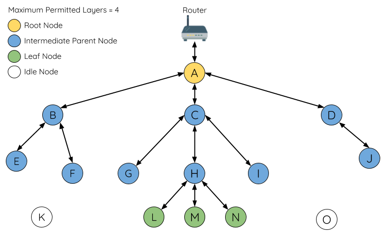
Root Node: The root node is the top node in the network and serves as the only interface between the ESP-MESH network and an external IP network. The root node is connected to a conventional Wi-Fi router and relays packets to/from the external IP network to nodes within the ESP-MESH network. There can only be one root node within an ESP-MESH network and the root node’s upstream connection may only be with the router. Referring to the diagram above, node A is the root node of the network.
Leaf Nodes: A leaf node is a node that is not permitted to have any child nodes (no downstream connections). Therefore a leaf node can only transmit or receive its own packets, but cannot forward the packets of other nodes. If a node is situated on the network’s maximum permitted layer, it will be assigned as a leaf node. This prevents the node from forming any downstream connections thus ensuring the network does not add an extra layer. Some nodes without a softAP interface (station only) will also be assigned as leaf nodes due to the requirement of a softAP interface for any downstream connections. Referring to the diagram above, nodes L/M/N are situated on the networks maximum permitted layer hence have been assigned as leaf nodes .
Intermediate Parent Nodes: Connected nodes that are neither the root node or a leaf node are intermediate parent nodes. An intermediate parent node must have a single upstream connection (a single parent node), but can have zero to multiple downstream connections (zero to multiple child nodes). Therefore an intermediate parent node can transmit and receive packets, but also forward packets sent from its upstream and downstream connections. Referring to the diagram above, nodes B to J are intermediate parent nodes. Intermediate parent nodes without downstream connections such as nodes E/F/G/I/J are not equivalent to leaf nodes as they are still permitted to form downstream connections in the future.
Idle Nodes: Nodes that have yet to join the network are assigned as idle nodes. Idle nodes will attempt to form an upstream connection with an intermediate parent node or attempt to become the root node under the correct circumstances (see Automatic Root Node Selection). Referring to the diagram above, nodes K and O are idle nodes.
Beacon Frames & RSSI Thresholding
Every node in ESP-MESH that is able to form downstream connections (i.e. has a softAP interface) will periodically transmit Wi-Fi beacon frames. A node uses beacon frames to allow other nodes to detect its presence and know of its status. Idle nodes will listen for beacon frames to generate a list of potential parent nodes, one of which the idle node will form an upstream connection with. ESP-MESH uses the Vendor Information Element to store metadata such as:
Node Type (Root, Intermediate Parent, Leaf, Idle)
Current layer of Node
Maximum number of layers permitted in the network
Current number of child nodes
Maximum number of downstream connections to accept
The signal strength of a potential upstream connection is represented by RSSI (Received Signal Strength Indication) of the beacon frames of the potential parent node. To prevent nodes from forming a weak upstream connection, ESP-MESH implements an RSSI threshold mechanism for beacon frames. If a node detects a beacon frame with an RSSI below a preconfigured threshold, the transmitting node will be disregarded when forming an upstream connection.
Effects of RSSI Thresholding
Panel A of the illustration above demonstrates how the RSSI threshold affects the number of parent node candidates an idle node has.
Panel B of the illustration above demonstrates how an RF shielding object can lower the RSSI of a potential parent node. Due to the RF shielding object, the area in which the RSSI of node X is above the threshold is significantly reduced. This causes the idle node to disregard node X even though node X is physically adjacent. The idle node will instead form an upstream connection with the physically distant node Y due to a stronger RSSI.
Note
Nodes technically still receive all beacon frames on the MAC layer. The RSSI threshold is an ESP-MESH feature that simply filters out all received beacon frames that are below the preconfigured threshold.
Preferred Parent Node
When an idle node has multiple parent nodes candidates (potential parent nodes), the idle node will form an upstream connection with the preferred parent node. The preferred parent node is determined based on the following criteria:
Which layer the parent node candidate is situated on
The number of downstream connections (child nodes) the parent node candidate currently has
The selection of the preferred parent node will always prioritize the parent node candidate on the shallowest layer of the network (including the root node). This helps minimize the total number of layers in an ESP-MESH network when upstream connections are formed. For example, given a second layer node and a third layer node, the second layer node will always be preferred.
If there are multiple parent node candidates within the same layer, the parent node candidate with the least child nodes will be preferred. This criteria has the effect of balancing the number of downstream connections amongst nodes of the same layer.
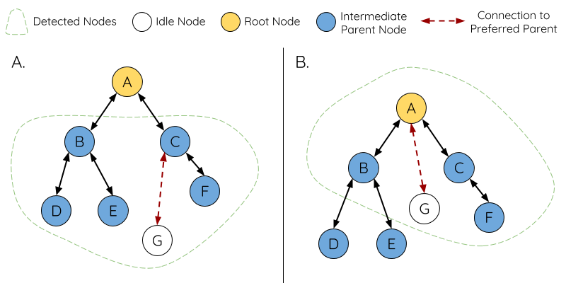
Preferred Parent Node Selection
Panel A of the illustration above demonstrates an example of how the idle node G selects a preferred parent node given the five parent node candidates B/C/D/E/F. Nodes on the shallowest layer are preferred, hence nodes B/C are prioritized since they are second layer nodes whereas nodes D/E/F are on the third layer. Node C is selected as the preferred parent node due it having fewer downstream connections (fewer child nodes) compared to node B.
Panel B of the illustration above demonstrates the case where the root node is within range of the idle node G. In other words, the root node’s beacon frames are above the RSSI threshold when received by node G. The root node is always the shallowest node in an ESP-MESH network hence is always the preferred parent node given multiple parent node candidates.
Note
Users may also define their own algorithm for selecting a preferred parent node, or force a node to only connect with a specific parent node (see the Mesh Manual Networking Example).
Routing Tables
Each node within an ESP-MESH network will maintain its individual routing table used to correctly route ESP-MESH packets (see ESP-MESH Packet) to the correct destination node. The routing table of a particular node will consist of the MAC addresses of all nodes within the particular node’s subnetwork (including the MAC address of the particular node itself). Each routing table is internally partitioned into multiple subtables with each subtable corresponding to the subnetwork of each child node.
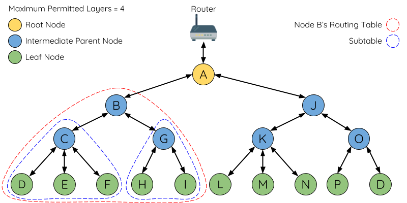
ESP-MESH Routing Tables Example
Using the diagram above as an example, the routing table of node B would consist of the MAC addresses of nodes B to I (i.e. equivalent to the subnetwork of node B). Node B’s routing table is internally partitioned into two subtables containing of nodes C to F and nodes G to I (i.e. equivalent to the subnetworks of nodes C and G respectively).
ESP-MESH utilizes routing tables to determine whether an ESP-MESH packet should be forwarded upstream or downstream based on the following rules.
1. If the packet’s destination MAC address is within the current node’s routing table and is not the current node, select the subtable that contains the destination MAC address and forward the data packet downstream to the child node corresponding to the subtable.
2. If the destination MAC address is not within the current node’s routing table, forward the data packet upstream to the current node’s parent node. Doing so repeatedly will result in the packet arriving at the root node where the routing table should contain all nodes within the network.
Note
Users can call esp_mesh_get_routing_table() to obtain a node’s routing table, or esp_mesh_get_routing_table_size() to obtain the size of a node’s routing table.
esp_mesh_get_subnet_nodes_list() can be used to obtain the corresponding subtable of a specific child node. Likewise esp_mesh_get_subnet_nodes_num() can be used to obtain the size of the subtable.
Building a Network
General Process
Warning
Before the ESP-MESH network building process can begin, certain parts of the configuration must be uniform across each node in the network (see mesh_cfg_t). Each node must be configured with the same Mesh Network ID, router configuration, and softAP configuration.
An ESP-MESH network building process involves selecting a root node, then forming downstream connections layer by layer until all nodes have joined the network. The exact layout of the network can be dependent on factors such as root node selection, parent node selection, and asynchronous power-on reset. However, the ESP-MESH network building process can be generalized into the following steps:
ESP-MESH Network Building Process
1. Root Node Selection
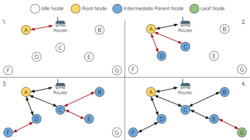
The root node can be designated during configuration (see section on User Designated Root Node), or dynamically elected based on the signal strength between each node and the router (see Automatic Root Node Selection). Once selected, the root node will connect with the router and begin allowing downstream connections to form. Referring to the figure above, node A is selected to be the root node hence node A forms an upstream connection with the router.
2. Second Layer Formation
Once the root node has connected to the router, idle nodes in range of the root node will begin connecting with the root node thereby forming the second layer of the network. Once connected, the second layer nodes become intermediate parent nodes (assuming maximum permitted layers > 2) hence the next layer to form. Referring to the figure above, nodes B to D are in range of the root node. Therefore nodes B to D form upstream connections with the root node and become intermediate parent nodes.
3. Formation of remaining layers
The remaining idle nodes will connect with intermediate parent nodes within range thereby forming a new layer in the network. Once connected, the idles nodes become intermediate parent node or leaf nodes depending on the networks maximum permitted layers. This step is repeated until there are no more idle nodes within the network or until the maximum permitted layer of the network has been reached. Referring to the figure above, nodes E/F/G connect with nodes B/C/D respectively and become intermediate parent nodes themselves.
4. Limiting Tree Depth
To prevent the network from exceeding the maximum permitted number of layers, nodes on the maximum layer will automatically become leaf nodes once connected. This prevents any other idle node from connecting with the leaf node thereby prevent a new layer form forming. However if an idle node has no other potential parent node, it will remain idle indefinitely. Referring to the figure above, the network’s number of maximum permitted layers is set to four. Therefore when node H connects, it becomes a leaf node to prevent any downstream connections from forming.
Automatic Root Node Selection
The automatic selection of a root node involves an election process amongst all idle nodes based on their signal strengths with the router. Each idle node will transmit their MAC addresses and router RSSI values via Wi-Fi beacon frames. The MAC address is used to uniquely identify each node in the network whilst the router RSSI is used to indicate a node’s signal strength with reference to the router.
Each node will then simultaneously scan for the beacon frames from other idle nodes. If a node detects a beacon frame with a stronger router RSSI, the node will begin transmitting the contents of that beacon frame (i.e. voting for the node with the stronger router RSSI). The process of transmission and scanning will repeat for a preconfigured minimum number of iterations (10 iterations by default) and result in the beacon frame with the strongest router RSSI being propagated throughout the network.
After all iterations, each node will individually check for its vote percentage (number of votes/number of nodes participating in election) to determine if it should become the root node. If a node has a vote percentage larger than a preconfigured threshold (90% by default), the node will become a root node.
The following diagram demonstrates how an ESP-MESH network is built when the root node is automatically selected.
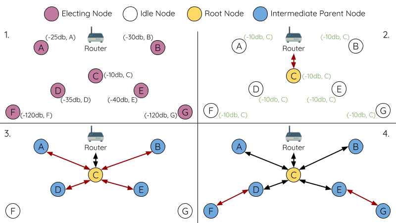
Root Node Election Example
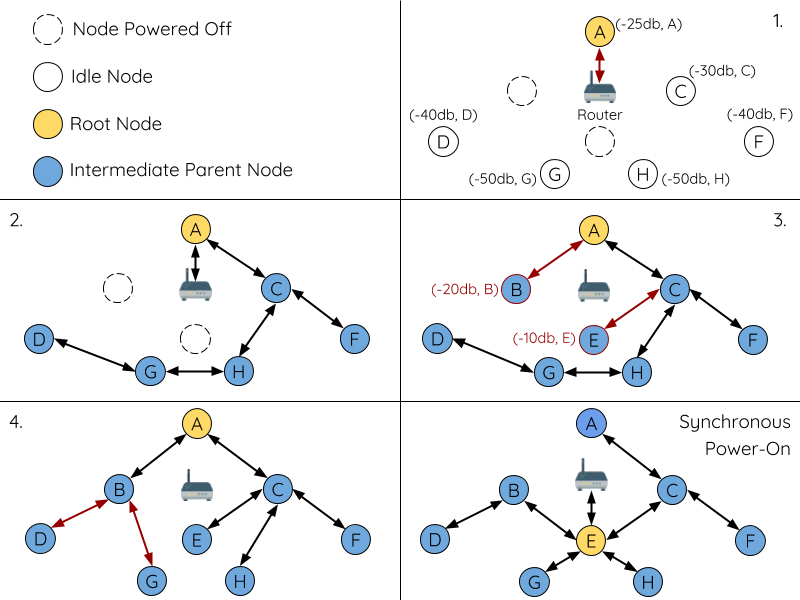
1. On power-on reset, each node begins transmitting beacon frames consisting of their own MAC addresses and their router RSSIs.
2. Over multiple iterations of transmission and scanning, the beacon frame with the strongest router RSSI is propagated throughout the network. Node C has the strongest router RSSI (-10 dB) hence its beacon frame is propagated throughout the network. All nodes participating in the election vote for node C thus giving node C a vote percentage of 100%. Therefore node C becomes a root node and connects with the router.
3. Once Node C has connected with the router, nodes A/B/D/E connectwith node C as it is the preferred parent node (i.e. the shallowest node). Nodes A/B/D/E form the second layer of the network.
4. Node F and G connect with nodes D and E respectively and the network building process is complete.
Note
The minimum number of iterations for the election process can be configured using esp_mesh_set_attempts(). Users should adjust the number of iterations based on the number of nodes within the network (i.e. the larger the network the larger number of scan iterations required).
Warning
Vote percentage threshold can also be configured using esp_mesh_set_vote_percentage(). Setting a low vote percentage threshold can result in two or more nodes becoming root nodes within the same ESP-MESH network leading to the building of multiple networks. If such is the case, ESP-MESH has internal mechanisms to autonomously resolve the root node conflict. The networks of the multiple root nodes will be combined into a single network with a single root node. However, root node conflicts where two or more root nodes have the same router SSID but different router BSSID are not handled.
User Designated Root Node
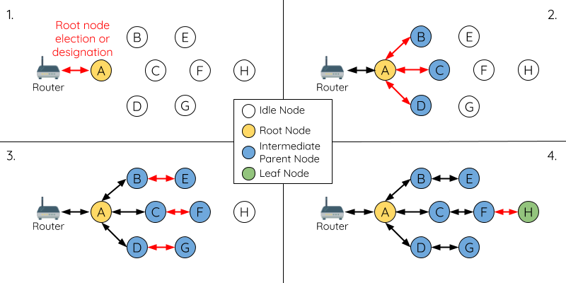
The root node can also be designated by user which will entail the designated root node to directly connect with the router and forgo the election process. When a root node is designated, all other nodes within the network must also forgo the election process to prevent the occurrence of a root node conflict. The following diagram demonstrates how an ESP-MESH network is built when the root node is designated by the user.
Root Node Designation Example (Root Node = A, Max Layers = 4)
1. Node A is designated the root node by the user therefore directly connects with the router. All other nodes forgo the election process.
2. Nodes C/D connect with node A as their preferred parent node. Both nodes form the second layer of the network.
3. Likewise, nodes B/E connect with node C, and node F connects with node D. Nodes B/E/F form the third layer of the network.
4. Node G connects with node E, forming the fourth layer of the network. However the maximum permitted number of layers in this network is configured as four, therefore node G becomes a leaf node to prevent any new layers from forming.
Note
When designating a root node, the root node should call esp_mesh_set_parent() in order to directly connect with the router. Likewise, all other nodes should call esp_mesh_fix_root() to forgo the election process.
Parent Node Selection
By default, ESP-MESH is self organizing meaning that each node will autonomously select which potential parent node to form an upstream connection with. The autonomously selected parent node is known as the preferred parent node. The criteria used for selecting the preferred parent node is designed to reduce the number of layers in the ESP-MESH network and to balance the number of downstream connections between potential parent nodes (see section on Preferred Parent Node).
However ESP-MESH also allows users to disable self-organizing behavior which will allow users to define their own criteria for parent node selection, or to configure nodes to have designated parent nodes (see the Mesh Manual Networking Example).
Asynchronous Power-on Reset
ESP-MESH network building can be affected by the order in which nodes power-on. If certain nodes within the network power-on asynchronously (i.e. separated by several minutes), the final structure of the network could differ from the ideal case where all nodes are powered on synchronously. Nodes that are delayed in powering on will adhere to the following rules:
Rule 1: If a root node already exists in the network, the delayed node will not attempt to elect a new root node, even if it has a stronger RSSI with the router. The delayed node will instead join the network like any other idle node by connecting with a preferred parent node. If the delayed node is the designated root node, all other nodes in the network will remain idle until the delayed node powers-on.
Rule 2: If a delayed node forms an upstream connection and becomes an intermediate parent node, it may also become the new preferred parent of other nodes (i.e. being a shallower node). This will cause the other nodes to switch their upstream connections to connect with the delayed node (see Parent Node Switching).
Rule 3: If an idle node has a designated parent node which is delayed in powering-on, the idle node will not attempt to form any upstream connections in the absence of its designated parent node. The idle node will remain idle indefinitely until its designated parent node powers-on.
The following example demonstrates the effects of asynchronous power-on with regards to network building.
Network Building with Asynchronous Power On Example
1. Nodes A/C/D/F/G/H are powered-on synchronously and begin the root node election process by broadcasting their MAC addresses and router RSSIs. Node A is elected as the root node as it has the strongest RSSI.
2. Once node A becomes the root node, the remaining nodes begin forming upstream connections layer by layer with their preferred parent nodes. The result is a network with five layers.
3. Node B/E are delayed in powering-on but neither attempt to become the root node even though they have stronger router RSSIs (-20 dB and -10 dB) compared to node A. Instead both delayed nodes form upstream connections with their preferred parent nodes A and C respectively. Both nodes B/E become intermediate parent nodes after connecting.
4. Nodes D/G switch their upstream connections as node B is the new preferred parent node due to it being on a shallower layer (second layer node). Due to the switch, the resultant network has three layers instead of the original five layers.
Synchronous Power-On: Had all nodes powered-on synchronously, node E would have become the root node as it has the strongest router RSSI (-10 dB). This would result in a significantly different network layout compared to the network formed under the conditions of asynchronous power-on. However the synchronous power-on network layout can still be reached if the user manually switches the root node (see esp_mesh_waive_root()).
Note
Differences in parent node selection caused by asynchronous power-on are autonomously corrected for to some extent in ESP-MESH (see Parent Node Switching)
Loop-back Avoidance, Detection, and Handling
A loop-back is the situation where a particular node forms an upstream connection with one of its descendant nodes (a node within the particular node’s subnetwork). This results in a circular connection path thereby breaking the tree topology. ESP-MESH prevents loop-back during parent selection by excluding nodes already present in the selecting node’s routing table (see Routing Tables) thus prevents a particular node from attempting to connect to any node within its subnetwork.
In the event that a loop-back occurs, ESP-MESH utilizes a path verification mechanism and energy transfer mechanism to detect the loop-back occurrence. The parent node of the upstream connection that caused the loop-back will then inform the child node of the loop-back and initiate a disconnection.
Managing a Network
ESP-MESH is a self healing network meaning it can detect and correct for failures in network routing. Failures occur when a parent node with one or more child nodes breaks down, or when the connection between a parent node and its child nodes becomes unstable. Child nodes in ESP-MESH will autonomously select a new parent node and form an upstream connection with it to maintain network interconnectivity. ESP-MESH can handle both Root Node Failures and Intermediate Parent Node Failures.
Root Node Failure
If the root node breaks down, the nodes connected with it (second layer nodes) will promptly detect the failure of the root node. The second layer nodes will initially attempt to reconnect with the root node. However after multiple failed attempts, the second layer nodes will initialize a new round of root node election. The second layer node with the strongest router RSSI will be elected as the new root node whilst the remaining second layer nodes will form an upstream connection with the new root node (or a neighboring parent node if not in range).
If the root node and multiple downstream layers simultaneously break down (e.g. root node, second layer, and third layer), the shallowest layer that is still functioning will initialize the root node election. The following example illustrates an example of self healing from a root node break down.
Self Healing From Root Node Failure
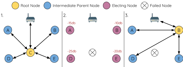
1. Node C is the root node of the network. Nodes A/B/D/E are second layer nodes connected to node C.
2. Node C breaks down. After multiple failed attempts to reconnect, the second layer nodes begin the election process by broadcasting their router RSSIs. Node B has the strongest router RSSI.
3. Node B is elected as the root node and begins accepting downstream connections. The remaining second layer nodes A/D/E form upstream connections with node B thus the network is healed and can continue operating normally.
Note
If a designated root node breaks down, the remaining nodes will not autonomously attempt to elect a new root node as an election process will never be attempted whilst a designated root node is used.
Intermediate Parent Node Failure
If an intermediate parent node breaks down, the disconnected child nodes will initially attempt to reconnect with the parent node. After multiple failed attempts to reconnect, each child node will begin to scan for potential parent nodes (see Beacon Frames & RSSI Thresholding).
If other potential parent nodes are available, each child node will individually select a new preferred parent node (see Preferred Parent Node) and form an upstream connection with it. If there are no other potential parent nodes for a particular child node, it will remain idle indefinitely.
The following diagram illustrates an example of self healing from an Intermediate Parent Node break down.
Self Healing From Intermediate Parent Node Failure
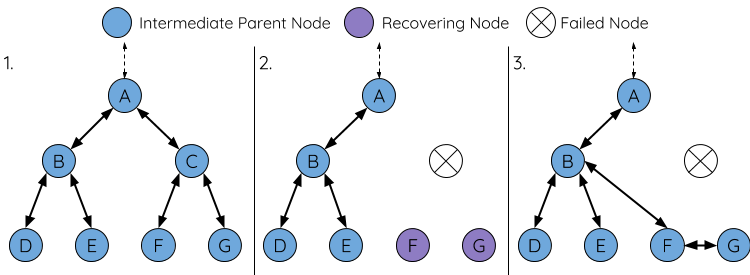
1. The following branch of the network consists of nodes A to G.
2. Node C breaks down. Nodes F/G detect the break down and attempt to reconnect with node C. After multiple failed attempts to reconnect, nodes F/G begin to select a new preferred parent node.
3. Node G is out of range from any other parent node hence remains idle for the time being. Node F is in range of nodes B/E, however node B is selected as it is the shallower node. Node F becomes an intermediate parent node after connecting with Node B thus node G can connect with node F. The network is healed, however the network routing as been affected and an extra layer has been added.
Note
If a child node has a designated parent node that breaks down, the child node will make no attempt to connect with a new parent node. The child node will remain idle indefinitely.
Root Node Switching
ESP-MESH does not automatically switch the root node unless the root node breaks down. Even if the root node’s router RSSI degrades to the point of disconnection, the root node will remain unchanged. Root node switching is the act of explicitly starting a new election such that a node with a stronger router RSSI will be elected as the new root node. This can be a useful method of adapting to degrading root node performance.
To trigger a root node switch, the current root node must explicitly call esp_mesh_waive_root() to trigger a new election. The current root node will signal all nodes within the network to begin transmitting and scanning for beacon frames (see Automatic Root Node Selection) whilst remaining connected to the network (i.e. not idle). If another node receives more votes than the current root node, a root node switch will be initiated. The root node will remain unchanged otherwise.
A newly elected root node sends a switch request to the current root node which in turn will respond with an acknowledgment signifying both nodes are ready to switch. Once the acknowledgment is received, the newly elected root node will disconnect from its parent and promptly form an upstream connection with the router thereby becoming the new root node of the network. The previous root node will disconnect from the router whilst maintaining all of its downstream connections and enter the idle state. The previous root node will then begin scanning for potential parent nodes and selecting a preferred parent.
The following diagram illustrates an example of a root node switch.
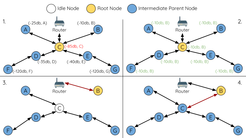
Root Node Switch Example
1. Node C is the current root node but has degraded signal strength with the router (-85db). The node C triggers a new election and all nodes begin transmitting and scanning for beacon frames whilst still being connected.
2. After multiple rounds of transmission and scanning, node B is elected as the new root node. Node B sends node C a switch request and node C responds with an acknowledgment.
3. Node B disconnects from its parent and connects with the router becoming the network’s new root node. Node C disconnects from the router, enters the idle state, and begins scanning for and selecting a new preferred parent node. Node C maintains all its downstream connections throughout this process.
4. Node C selects node B as its preferred parent node, forms an upstream connection, and becomes a second layer node. The network layout is similar after the switch as node C still maintains the same subnetwork. However each node in node C’s subnetwork has been placed one layer deeper as a result of the switch. Parent Node Switching may adjust the network layout afterwards if any nodes have a new preferred parent node as a result of the root node switch.
Note
Root node switching must require an election hence is only supported when using a self-organized ESP-MESH network. In other words, root node switching cannot occur if a designated root node is used.
Parent Node Switching
Parent Node Switching entails a child node switching its upstream connection to another parent node of a shallower layer. Parent Node Switching occurs autonomously meaning that a child node will change its upstream connection automatically if a potential parent node of a shallower layer becomes available (i.e. due to a Asynchronous Power-on Reset).
All potential parent nodes periodically transmit beacon frames (see Beacon Frames & RSSI Thresholding) allowing for a child node to scan for the availability of a shallower parent node. Due to parent node switching, a self-organized ESP-MESH network can dynamically adjust its network layout to ensure each connection has a good RSSI and that the number of layers in the network is minimized.
Data Transmission
ESP-MESH Packet
ESP-MESH network data transmissions use ESP-MESH packets. ESP-MESH packets are entirely contained within the frame body of a Wi-Fi data frame. A multi-hop data transmission in an ESP-MESH network will involve a single ESP-MESH packet being carried over each wireless hop by a different Wi-Fi data frame.
The following diagram shows the structure of an ESP-MESH packet and its relation with a Wi-Fi data frame.
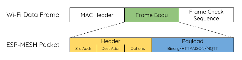
ESP-MESH Packet
The header of an ESP-MESH packet contains the MAC addresses of the source and destination nodes. The options field contains information pertaining to the special types of ESP-MESH packets such as a group transmission or a packet originating from the external IP network (see MESH_OPT_SEND_GROUP and MESH_OPT_RECV_DS_ADDR).
The payload of an ESP-MESH packet contains the actual application data. This data can be raw binary data, or encoded under an application layer protocol such as HTTP, MQTT, and JSON (see mesh_proto_t).
Note
When sending an ESP-MESH packet to the external IP network, the destination address field of the header will contain the IP address and port of the target server rather than the MAC address of a node (see mesh_addr_t). Furthermore the root node will handle the formation of the outgoing TCP/IP packet.
Group Control & Multicasting
Multicasting is a feature that allows a single ESP-MESH packet to be transmitted simultaneously to multiple nodes within the network. Multicasting in ESP-MESH can be achieved by either specifying a list of target nodes, or specifying a preconfigured group of nodes. Both methods of multicasting are called via esp_mesh_send().
To multicast by specifying a list of target nodes, users must first set the ESP-MESH packet’s destination address to the Multicast-Group Address (01:00:5E:xx:xx:xx). This signifies that the ESP-MESH packet is a multicast packet with a group of addresses, and that the address should be obtained from the header options. Users must then list the MAC addresses of the target nodes as options (see mesh_opt_t and MESH_OPT_SEND_GROUP). This method of multicasting requires no prior setup but can incur a large amount of overhead data as each target node’s MAC address must be listed in the options field of the header.
Multicasting by group allows a ESP-MESH packet to be transmitted to a preconfigured group of nodes. Each grouping is identified by a unique ID, and a node can be placed into a group via esp_mesh_set_group_id(). Multicasting to a group involves setting the destination address of the ESP-MESH packet to the target group ID. Furthermore, the MESH_DATA_GROUP flag must set. Using groups to multicast incurs less overhead, but requires nodes to previously added into groups.
Note
During a multicast, all nodes within the network still receive the ESP-MESH packet on the MAC layer. However, nodes not included in the MAC address list or the target group will simply filter out the packet.
Broadcasting
Broadcasting is a feature that allows a single ESP-MESH packet to be transmitted simultaneously to all nodes within the network. Each node essentially forwards a broadcast packet to all of its upstream and downstream connections such that the packet propagates throughout the network as quickly as possible. However, ESP-MESH utilizes the following methods to avoid wasting bandwidth during a broadcast.
1. When an intermediate parent node receives a broadcast packet from its parent, it will forward the packet to each of its child nodes whilst storing a copy of the packet for itself.
2. When an intermediate parent node is the source node of the broadcast, it will transmit the broadcast packet upstream to is parent node and downstream to each of its child nodes.
3. When an intermediate parent node receives a broadcast packet from one of its child nodes, it will forward the packet to its parent node and each of its remaining child nodes whilst storing a copy of the packet for itself.
4. When a leaf node is the source node of a broadcast, it will directly transmit the packet to its parent node.
5. When the root node is the source node of a broadcast, the root node will transmit the packet to all of its child nodes.
6. When the root node receives a broadcast packet from one of its child nodes, it will forward the packet to each of its remaining child nodes whilst storing a copy of the packet for itself.
7. When a node receives a broadcast packet with a source address matching its own MAC address, the node will discard the broadcast packet.
8. When an intermediate parent node receives a broadcast packet from its parent node which was originally transmitted from one of its child nodes, it will discard the broadcast packet
Upstream Flow Control
ESP-MESH relies on parent nodes to control the upstream data flow of their immediate child nodes. To prevent a parent node’s message buffer from overflowing due to an overload of upstream transmissions, a parent node will allocate a quota for upstream transmissions known as a receiving window for each of its child nodes. Each child node must apply for a receiving window before it is permitted to transmit upstream. The size of a receiving window can be dynamically adjusted. An upstream transmission from a child node to the parent node consists of the following steps:
1. Before each transmission, the child node sends a window request to its parent node. The window request consists of a sequence number which corresponds to the child node’s data packet that is pending transmission.
2. The parent node receives the window request and compares the sequence number with the sequence number of the previous packet sent by the child node. The comparison is used to calculate the size of the receiving window which is transmitted back to the child node.
3. The child node transmits the data packet in accordance with the window size specified by the parent node. If the child node depletes its receiving window, it must obtain another receiving windows by sending a request before it is permitted to continue transmitting.
Note
ESP-MESH does not support any downstream flow control.
Warning
Due to Parent Node Switching, packet loss may occur during upstream transmissions.
Due to the fact that the root node acts as the sole interface to an external IP network, it is critical that downstream nodes are aware of the root node’s connection status with the external IP network. Failing to do so can lead to nodes attempting to pass data upstream to the root node whilst it is disconnected from the IP network. This results in unnecessary transmissions and packet loss. ESP-MESH address this issue by providing a mechanism to stabilize the throughput of outgoing data based on the connection status between the root node and the external IP network. The root node can broadcast its external IP network connection status to all other nodes by calling esp_mesh_post_toDS_state().
Bi-Directional Data Stream
The following diagram illustrates the various network layers involved in an ESP-MESH Bidirectional Data Stream.
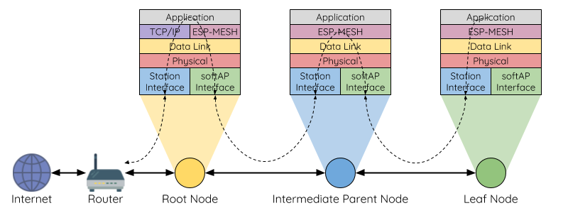
ESP-MESH Bidirectional Data Stream
Due to the use of Routing Tables, ESP-MESH is able to handle pack forwarding entirely on the mesh layer. A TCP/IP layer is only required on the root node when it transmits/receives a packet to/from an external IP network.
Channel Switching
Background
In traditional Wi-Fi networks, channels are predetermined frequency ranges. In an infrastructure basic service set (BSS), the serving AP and its connected stations must be on the same operating channels (1 to 14) in which beacons are transmitted. Physically adjacent BSS (Basic Service Sets) operating on the same channel can lead to interference and degraded performance.
In order to allow a BSS adapt to changing physical layer conditions and maintain performance, Wi-Fi contains mechanisms for network channel switching. A network channel switch is an attempt to move a BSS to a new operating channel whilst minimizing disruption to the BSS during this process. However it should be recognized that a channel switch may be unsuccessful in moving all stations to the new operating channel.
In an infrastructure Wi-Fi network, network channel switches are triggered by the AP with the aim of having the AP and all connected stations synchronously switch to a new channel. Network channel switching is implemented by embedding a Channel Switch Announcement (CSA) element within the AP’s periodically transmitted beacon frames. The CSA element is used to advertise to all connected stations regarding an upcoming network channel switch and will be included in multiple beacon frames up until the switch occurs.
A CSA element contains information regarding the New Channel Number and a Channel Switch Count which indicates the number of beacon frame intervals (TBTTs) remaining until the network channel switch occurs. Therefore, the Channel Switch Count is decremented every beacon frame and allows connected stations to synchronize their channel switch with the AP.
ESP-MESH Network Channel Switching
ESP-MESH Network Channel Switching also utilize beacon frames that contain a CSA element. However, being a multi-hop network makes the switching process in ESP-MESH is more complex due to the fact that a beacon frame might not be able to reach all nodes within the network (i.e. in a single hop). Therefore, an ESP-MESH network relies on nodes to forward the CSA element so that it is propagated throughout the network.
When an intermediate parent node with one or more child nodes receives a beacon frame containing a CSA, the node will forward the CSA element by including the element in its next transmitted beacon frame (i.e. with the same New Channel Number and Channel Switch Count). Given that all nodes within an ESP-MESH network receive the same CSA, the nodes can synchronize their channel switches using the Channel Switch Count, albeit with a short delay due to CSA element forwarding.
An ESP-MESH network channel switch can be triggered by either the router or the root node.
Root Node Triggered
A root node triggered channel switch can only occur when the ESP-MESH network is not connected to a router. By calling esp_mesh_switch_channel(), the root node will set an initial Channel Switch Count value and begin including a CSA element in its beacon frames. Each CSA element is then received by second layer nodes, and forwarded downstream in the their own beacon frames.
Router Triggered
When an ESP-MESH network is connected to a router, the entire network must use the same channel as the router. Therefore, the root node will not be permitted to trigger a channel switch when it is connected to a router.
When the root node receives beacon frame containing a CSA element from the router, the root node will set Channel Switch Count value in the CSA element to a custom value before forwarding it downstream via beacon frames. It will also decrement the Channel Switch Count of subsequent CSA elements relative to the custom value. This custom value can be based on factors such as the number of network layers, the current number of nodes etc.
The setting the Channel Switch Count value to a custom value is due to the fact that the ESP-MESH network and its router may have a different and varying beacon intervals. Therefore, the Channel Switch Count value provided by the router is irrelevant to an ESP-MESH network. By using a custom value, nodes within the ESP-MESH network are able to switch channels synchronously relative to the ESP-MESH network’s beacon interval. However, this will also result in the ESP-MESH network’s channel switch being unsynchronized with the channel switch of the router and its connected stations.
Impact of Network Channel Switching
- Due to the ESP-MESH network channel switch being unsynchronized with the router’s channel switch, there will be a temporary channel discrepancy between the ESP-MESH network and the router.
The ESP-MESH network’s channel switch time is dependent on the ESP-MESH network’s beacon interval and the root node’s custom Channel Switch Count value.
The channel discrepancy prevents any data exchange between the root node and the router during that ESP-MESH network’s switch.
In the ESP-MESH network, the root node and intermediate parent nodes will request their connected child nodes to stop transmissions until the channel switch takes place by setting the Channel Switch Mode field in the CSA element to 1.
Frequent router triggered network channel switches can degrade the ESP-MESH network’s performance. Note that this can be caused by the ESP-MESH network itself (e.g. due to wireless medium contention with ESP-MESH network). If this is the case, users should disable the automatic channel switching on the router and use a specified channel instead.
- When there is a temporary channel discrepancy, the root node remains technically connected to the router.
Disconnection occurs after the root node fails to receive any beacon frames or probe responses from the router over a fixed number of router beacon intervals.
Upon disconnection, the root node will automatically re-scan all channels for the presence of a router.
- If the root node is unable to receive any of the router’s CSA beacon frames (e.g. due to short switch time given by the router), the router will switch channels without the ESP-MESH network’s knowledge.
After the router switches channels, the root node will no longer be able to receive the router’s beacon frames and probe responses and result in a disconnection after a fixed number of beacon intervals.
The root node will re-scan all channels for the router after disconnection.
The root node will maintain downstream connections throughout this process.
Note
Although ESP-MESH network channel switching aims to move all nodes within the network to a new operating channel, it should be recognized that a channel switch might not successfully move all nodes (e.g. due to reasons such as node failures).
Channel and Router Switching Configuration
ESP-MESH allows for autonomous channel switching to be enabled/disabled via configuration. Likewise, autonomous router switching (i.e. when a root node autonomously connects to another router) can also be enabled/disabled by configuration. Autonomous channel switching and router switching is dependent on the following configuration parameters and run-time conditions.
Allow Channel Switch: This parameter is set via the allow_channel_switch field of the mesh_cfg_t structure and permits an ESP-MESH network to dynamically switch channels when set.
Preset Channel: An ESP-MESH network can have a preset channel by setting the channel field of the mesh_cfg_t structure to the desired channel number. If this field is unset, the allow_channel_switch parameter is overridden such that channel switches are always permitted.
Allow Router Switch: This parameter is set via the allow_router_switch field of the mesh_router_t and permits an ESP-MESH to dynamically switch to a different router when set.
Preset Router BSSID: An ESP-MESH network can have a preset router by setting the bssid field of the mesh_router_t structure to the
BSSID of the desired router. If this field is unset, the allow_router_switch parameter is overridden such that router switches are always permitted.
Root Node Present: The presence of a root node will can also affect whether or a channel or router switch is permitted.
The following table illustrates how the different combinations of parameters/conditions affect whether channel switching and/or router switching is permitted. Note that X represents a “don’t care” for the parameter.
Preset Channel |
Allow Channel Switch |
Preset Router BSSID |
Allow Router Switch |
Root Node Present |
Permitted Switches? |
|---|---|---|---|---|---|
N |
X |
N |
X |
X |
Channel and Router |
N |
X |
Y |
N |
X |
Channel Only |
N |
X |
Y |
Y |
X |
Channel and Router |
Y |
Y |
N |
X |
X |
Channel and Router |
Y |
N |
N |
X |
N |
Router Only |
Y |
N |
N |
X |
Y |
Channel and Router |
Y |
Y |
Y |
N |
X |
Channel Only |
Y |
N |
Y |
N |
N |
N |
Y |
N |
Y |
N |
Y |
Channel Only |
Y |
Y |
Y |
Y |
X |
Channel and Router |
Y |
N |
Y |
Y |
N |
Router Only |
Y |
N |
Y |
Y |
Y |
Channel and Router |
Performance
The performance of an ESP-MESH network can be evaluated based on multiple metrics such as the following:
Network Building Time: The amount of time taken to build an ESP-MESH network from scratch.
Healing Time: The amount of time taken for the network to detect a node break down and carry out appropriate actions to heal the network (such as generating a new root node or forming new connections).
Per-hop latency: The latency of data transmission over one wireless hop. In other words, the time taken to transmit a data packet from a parent node to a child node or vice versa.
Network Node Capacity: The total number of nodes the ESP-MESH network can simultaneously support. This number is determined by the maximum number of downstream connections a node can accept and the maximum number of layers permissible in the network.
The following table lists the common performance figures of an ESP-MESH network:
Network Building Time: < 60 seconds
- Healing time:
Root node break down: < 10 seconds
Child node break down: < 5 seconds
Per-hop latency: 10 to 30 milliseconds
Note
The following test conditions were used to generate the performance figures above.
Number of test devices: 100
Maximum Downstream Connections to Accept: 6
Maximum Permissible Layers: 6
Note
Throughput depends on packet error rate and hop count.
Note
The throughput of root node’s access to the external IP network is directly affected by the number of nodes in the ESP-MESH network and the bandwidth of the router.
Note
The performance figures can vary greatly between installations based on network configuration and operating environment.
Further Notes
Data transmission uses Wi-Fi WPA2-PSK encryption
Mesh networking IE uses AES encryption
Router and internet icon made by Smashicons from www.flaticon.com