Programming Serial Port Detection and Troubleshooting
Note
This document is automatically translated using AI. Please excuse any detailed errors. The official English version is still in progress.
This document aims to systematically explain the complete process of ESP firmware programming, including hardware wiring, serial port connection, download mode triggering, programming operation, and troubleshooting methods and ideas for each link.
Note
The term “chip” in the document uniformly refers to ESP series chips or modules.
Hardware Wiring
Note
If you are using the ESP development board for firmware programming, you can skip this step.
Before using the ESP chip for firmware programming, you need to first complete the hardware environment setup to ensure that the chip can be powered on smoothly and program download can be performed.
Power supply and reset: Corresponding to the 3V3 and EN pins, it is necessary to ensure that the chip power supply is stable, the startup level meets the specification requirements, and the reset pin (EN) can be triggered normally, to avoid startup failure or functional abnormalities caused by unstable power supply or abnormal pin status.
programming interface: Corresponding to the UART0 or USB interface, it is necessary to ensure that the interface used for firmware download (such as UART, USB, etc.) is correctly connected to avoid unstable communication leading to programming failure.
Download mode pin: Corresponding to the strapping pin, when programming firmware, it must be ensured that the chip is in download mode. The entry into download mode is related to the specific pin status (strapping pin) of the chip. Therefore, during the hardware environment setup stage, it is necessary to reasonably design the wiring method of these pins to ensure that the download mode can be entered to complete the firmware programming. Depending on the wiring method, there are two common schemes: manual download mode and automatic download mode.
Manual download mode: Triggered by user operation to enter download mode, the wiring is simple, suitable for small-scale programming or development debugging scenarios.
Automatic download mode: The chip can automatically enter the download mode upon power-up, suitable for batch programming, but requires additional wiring during the hardware design stage.
These tasks are the basis of hardware environment setup, providing reliable conditions for firmware programming, function debugging, and stable system operation.
Different models of ESP chips may have differences in hardware environment requirements (such as pin definitions, power supply specifications), and specific details can be referred to the Hardware Requirements for Entering Download Mode on Different ESP Chips document. The wiring schemes in the document are all designed for manual download mode, which is convenient for firmware programming.
Note
It is recommended to implement the circuit design of automatic download mode during the subsequent hardware design stage. This way, you can quickly switch between firmware programming and firmware running without the need for additional manual hardware environment configuration.
Serial Port Connection
After completing the hardware wiring, it is necessary to establish a serial connection between the chip or development board and the computer through the corresponding interface for subsequent data transmission. Currently, there are mainly the following two interfaces:
UART: Requires a USB to UART converter chip
USB: Requires ESP chip itself to support USB Serial/JTAG
You can refer to the Establishing a Serial Connection page to check and confirm that the port is correctly identified, ensuring a stable serial connection. This page by default displays information related to the ESP32-S3 chip. If you need to view content for other chips, you can switch the chip model through the option in the upper left corner of the linked page.
If you encounter any problems, please refer to the Serial Connection section in the Troubleshooting chapter.
Download Mode
Download mode (Joint Download Boot) is a special boot mode used by ESP series chips for firmware programming and debugging. In this mode, the chip will not boot the application from Flash, but waits to receive new firmware data through interfaces such as UART or USB, and writes it to Flash or runs it directly in SRAM.
Whether the chip enters download mode is determined by the strapping pin level detected at power-up or reset. At the moment of power-up or reset, the chip reads the level status of these pins and selects the boot mode accordingly. When the pins are configured to the level corresponding to download mode, the chip will enter download mode and wait for the download tool to connect. The definitions and level requirements of strapping pins vary for different chips. For specific pin numbers and triggering steps, refer to the strapping pins page. This page by default displays information related to the ESP32-S3 chip. If you need to view content for other chips, you can switch the chip model through the option in the upper left corner of the linked page.
Note
ESP development boards are all designed for automatic download mode.
If the circuit is designed for automatic download mode, the chip will automatically enter download mode when the strapping pin levels are detected; if the automatic download mode circuit is not designed, you can also manually enter download mode.
You can further confirm whether the ESP chip has successfully entered download mode through the serial debugging tool, such as the following log output:
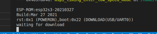
If the serial debugging tool displays “waiting for download” and other related prompt information, it indicates that the module has successfully entered download mode.
programming Operation
After completing the serial connection and confirming that the chip or development board is in download mode, you can carry out the firmware programming operation. There are differences in the selection of programming tools and the way to obtain firmware in different software development scenarios:
Refer to Obtain firmware programming information for different software development platforms to understand the firmware generation method and programming parameter requirements.
Refer to Choosing the Appropriate Flashing Platform to select a flashing platform that suits your needs, and follow the steps to complete the flashing operation.
Troubleshooting
Serial Port Connection
Cannot Find Serial Port in Device Manager
If the serial port cannot be correctly identified when using the USB interface, you can first confirm whether the USB-Serial-JTAG peripheral driver has been installed through the USB-Serial-JTAG Peripheral Driver Installation Steps document. If it has not been installed, follow the steps provided in the document to install the driver. If the serial port still cannot be recognized or the serial port is automatically disconnected, you can refer to the USB FAQ for troubleshooting.
Note
If the problem still persists, please refer to the Troubleshooting section of the official ESPTool documentation.