Espressif Flashing Tools
This section introduces the flashing solutions under the Espressif chip ecosystem, including flashing boards, test fixtures, and ESP-PROG debugging download tools.
For the selection of Espressif flashing boards and test fixtures, refer to Espressif official flashing accessories.
For the selection of ESP-PROG debugging download tools, refer to Espressif other IoT development boards
For documentation, refer to: User guide for debugging and flashing Espressif development boards
Introduction to Espressif Flashing board
“Flashing board” refers to a type of standard hardware accessory designed by Espressif for firmware flashing and software testing preparation for ESP series modules. Its main functions are:
Provide stable power supply and serial port connection for the module without soldering the module to the whole machine circuit board
Integrated Boot and Reset control buttons, support the module to quickly enter the download mode
Expose the I/O pins of the module for easy basic function verification and development debugging
Main structure and working mode of the flashing board
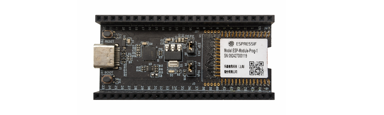
Taking the Espressif standard module flashing board as an example, the typical structure includes:
Pin springs
Dock with the module’s stamp hole to achieve power and signal connection.
Female headers J2/J3 (2.54 mm):
Expose the pins of the module for easy use as a development board;
J2/J3 are marked with signals such as 3V3, 5V, EN, GND, and P1~P44.
USB Type‑C to UART interface:
Power supply + serial communication (recommended default power supply method).
Boot button / Reset button (EN):
Boot button: Hold down Boot and then press Reset to enter the firmware download mode.
Reset button: Reset the module.
J4 (Strapping pin selection):
One end is connected to P7, and the other end is connected to High. The jumper cap determines whether P7 is pulled up to adapt to the strapping needs of different modules. For detailed explanation, refer to Strapping pin status selection.
J5 (Current measurement pin header):
Remove the jumper: You can measure the module current by connecting an ammeter in series at J5. For detailed instructions, refer to Measuring Current.
Install the jumper: Restore normal power supply.
How to Use the Flashing board
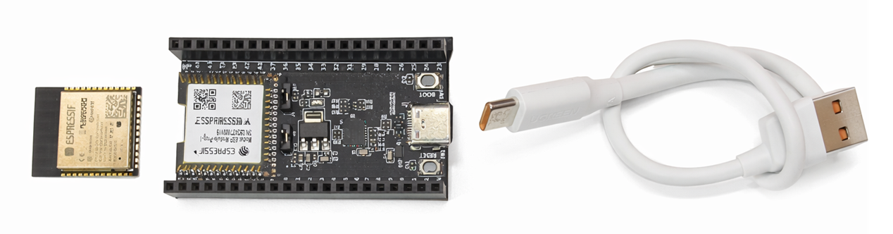
Hardware Installation Steps
Gently place the module in the spring pin area of the main board, aligning with the stamp hole.
Press down the module, a “click” sound indicates that the spring pin has been inserted into the hole.
Check whether all spring pins have entered the stamp hole. If there is any misalignment, adjust it with tweezers.
Connect to the computer via USB Type-C (or power supply via 5V/3V3 pin).
Note
Note: Please use a USB cable that supports data transfer. Some cables can only charge and cannot flash.
The flashing board is mainly used for R&D debugging, small batch verification, and engineering testing scenarios.
For detailed usage instructions, refer to:
Espressif Test Fixture Introduction
Espressif’s test fixture is mainly used on the production line for batch firmware flashing and function/RF production testing of ESP series modules. It is a dedicated tool used in conjunction with the official Flash download tool and PC software. Its core function is: through reliable contact between the probe and the module pad, the module’s power, serial port, and test signals are led out to the production test board/PC, realizing automated batch testing and flashing. It supports one-to-four multi-module parallel flashing, significantly improving mass production efficiency.
Main Structure and Working Method of the Fixture
Taking the Espressif standard module fixture as an example, the typical structure includes:
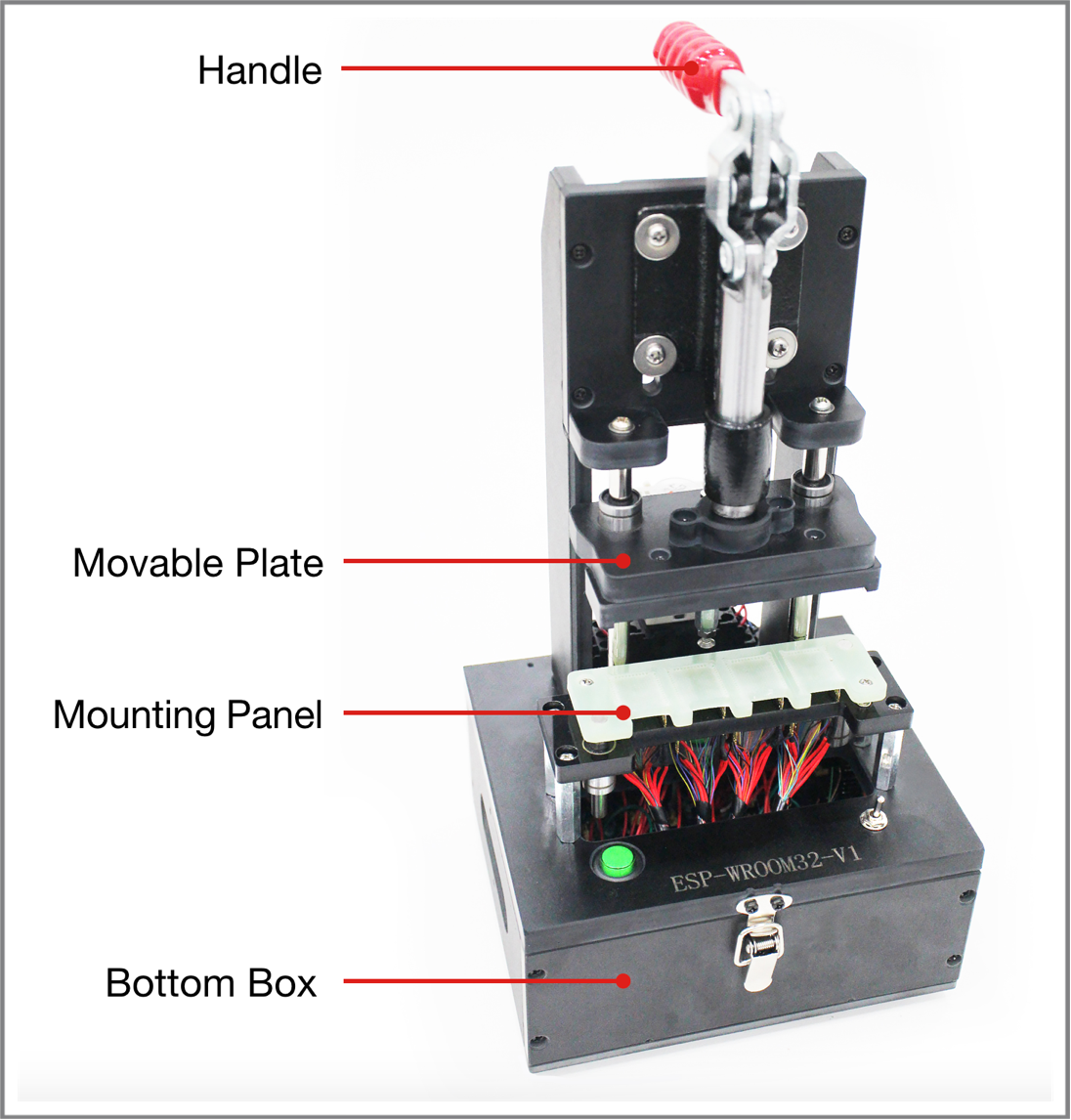
Handle
Lift: The module is separated from the bottom spring probe, power off.
Press: The module is pressed on the probe, all necessary pins are connected, and the module is powered on and enters the test state.
Module Platform
Used to place and position the module, ensuring that the pads and probes correspond one-to-one.
The antenna area must be completely exposed, the module platform must not use metal, and metal parts should be minimized near the antenna to avoid affecting RF performance.
Bottom Box
The internal serial port test board (such as ESP_Factory Test Board V1.3) is installed, connected to the PC via a USB cable, used for power supply and serial communication.
The board needs to be fixed with screws to prevent short circuits caused by movement.
Switch
Installed on the bottom box, used to control whether to power the module, and to switch different working modes (such as entering test mode) through dialing/pressing buttons.
Probes and Wiring
The spring probe pushes up from the bottom to the module pad, and is led out to the board through the red Dupont wire, corresponding pins are paralleled.
The wire requirements are as short as possible, with appropriate thickness, and unused pins should not be wired to avoid interference.
Role of the test Fixture in the Mass Production Process
In the ESP mass production process, the test fixture mainly cooperates with the following work:
Batch Firmware and Parameter Burning
Connect the module to the PC through the test fixture, use ESP Flash Download Tool or esptool to batch burn application firmware, device certificates, eFuse configurations, etc.
Production Line Automation Testing
With the “Espressif Production Testing Tool” (one-to-four host machine) and signal board (such as ESP-BAT8, etc.), complete RF performance testing, GPIO conduction testing, Flash reading and writing, version verification, etc., and automatically generate test logs and reports.
Standardization and Consistency
Through unified test fixture manufacturing specifications, reduce contact failures, RF performance fluctuations, and misjudgments caused by fixture differences, and improve testing efficiency and yield.
Espressif’s mass production test fixture is mainly used in large-scale industrial production scenarios, which can effectively improve the efficiency of batch firmware deployment, while ensuring the consistency of product configuration and the controllability of the production process.
For detailed usage instructions, see:
Espressif Development Debugging Tools Introduction
ESP-PROG / ESP-PROG-2 are high-performance development debugging tools launched by Espressif, specifically designed for embedded system software development and debugging optimization. This tool integrates automatic firmware download, serial communication, and JTAG online debugging capabilities, which can effectively simplify the development process and improve system debugging efficiency, and is widely applicable to IoT device development and maintenance scenarios. Its core functional features include:
High-speed Firmware Download and Communication Capabilities
Provide Program communication interface, support automatic download and serial communication functions, can achieve fast firmware burning and device interaction, significantly shorten the development verification cycle.
JTAG Online Debugging Support
Provide JTAG interface for implementing online debugging functions of ESP chips, support program running status tracking, breakpoint setting and variable monitoring, help developers efficiently locate software abnormal problems.
Multi-chip Debugging Architecture Compatibility
Support various embedded chip debugging needs, suitable for complex system development environments, can meet multi-device collaborative debugging and problem analysis scenarios.
Standard Toolchain Ecosystem Support
Can seamlessly cooperate with mainstream development debugging software (OpenOCD + GDB, etc.) and compilation toolchains, support system-level software development, testing verification, and troubleshooting work.
ESP-PROG / ESP-PROG-2 Usage Steps
For detailed usage instructions, see:
ESP-PROG / ESP-PROG-2 provides developers with an efficient, stable, and easy-to-use debugging solution, which is an indispensable auxiliary tool in the process of embedded software engineering development.
Classification of Tool Application Stages
Tool Type |
Applicable Stage |
Typical Use Case |
|---|---|---|
Flashing Board |
R&D Verification/Small Batch |
Module Function Debugging and Small Batch Burning |
ESP-PROG |
Software Debugging Development |
Online Debugging and Problem Location |
Mass Production Burning Fixture |
Mass Production |
Large-scale Mass Burning Deployment |