USB Device Stack
Overview
The ESP-IDF USB Device Stack (hereinafter referred to as the Device Stack) enables USB Device support on ESP32-S2. By using the Device Stack, ESP32-S2 can be programmed with any well defined USB device functions (e.g., keyboard, mouse, camera), a custom function (aka vendor-specific class), or a combination of those functions (aka a composite device).
The Device Stack is built around the TinyUSB stack, but extends TinyUSB with some minor features and modifications for better integration with ESP-IDF. The Device stack is distributed as a managed component via the ESP Component Registry.
Features
Multiple supported device classes (CDC, HID, MIDI, MSC)
Composite devices
Vendor specific classes
Maximum of 6 endpoints
5 IN/OUT endpoints
1 IN endpoints
VBUS monitoring for self-powered devices
Hardware Connection
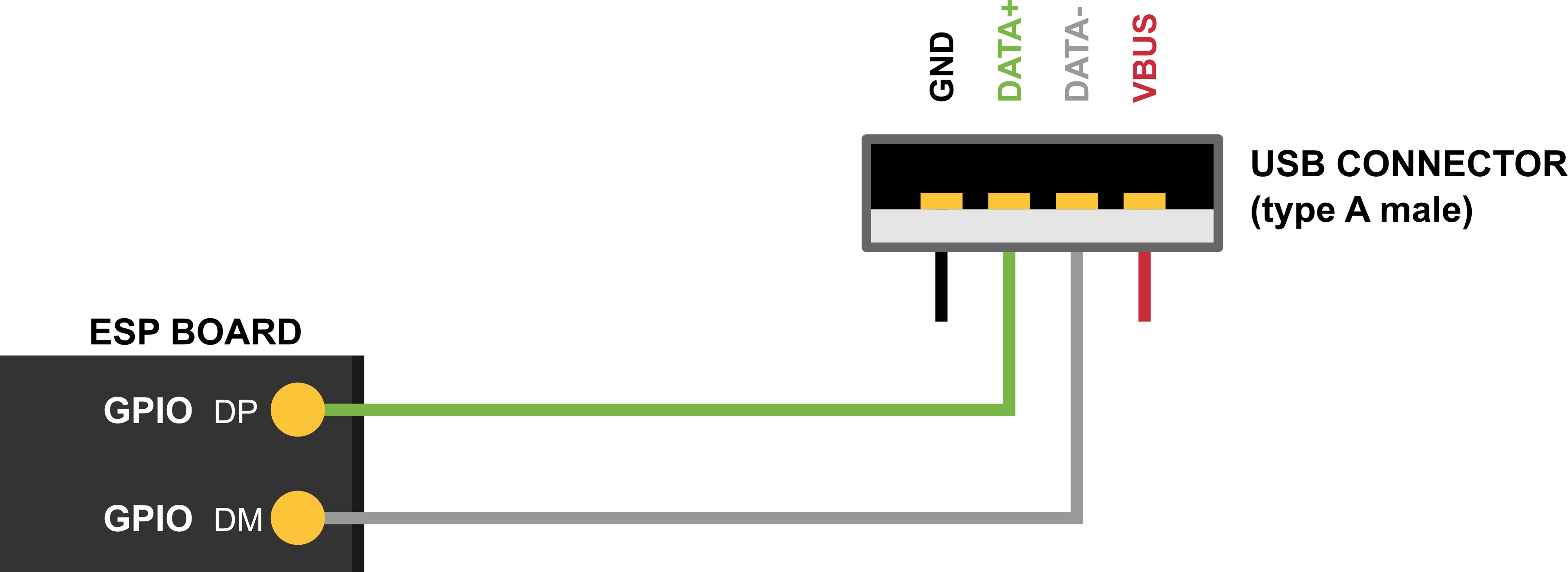
The ESP32-S2 routes the USB D+ and D- signals to GPIOs 20 and 19 respectively. For USB device functionality, these GPIOs should be connected to the bus in some way (e.g., via a Micro-B port, USB-C port, or directly to standard-A plug).

Note
If you are using an ESP32-S2 development board with two USB ports, the port labeled "USB" will already be connected to the D+ and D- GPIOs.
Note
Self-powered devices must also connect VBUS through a voltage divider or comparator. For more details, please refer to Self-Powered Device.
Device Stack Structure
The basis of the Device Stack is TinyUSB, where the Device Stack implements the following features on top of TinyUSB:
Customization of USB descriptors
Serial device support
Redirecting of standard streams through the Serial device
Storage Media (SPI-Flash and SD-Card) for USB Device MSC Class.
A task within the encapsulated device stack that handles TinyUSB servicing
Component Dependency
The Device Stack is distributed via the ESP Component Registry. Thus, to use it, please add the Device Stack component as dependency using the following command:
idf.py add-dependency esp_tinyusb
Configuration Options
Multiple aspects of the Device Stack can be configured using menuconfig. These include:
The verbosity of the TinyUSB's log
Device Stack task related options
Default device/string descriptor options
Class specific options
Descriptor Configuration
The tinyusb_config_t structure provides USB descriptor related fields that should be initialized.
The following descriptors should be initialized for both full-speed and high-speed devices:
device_descriptorstring_descriptor
Full-speed devices should initialize the following field to provide their configuration descriptor:
configuration_descriptor
The Device Stack will instantiate a USB device based on the descriptors provided in the fields described above when tinyusb_driver_install() is called.
The Device Stack also provides default descriptors that can be installed by setting the corresponding field in tinyusb_driver_install() to NULL. Default descriptors include:
Default device descriptor: Enabled by setting
device_descriptortoNULL. Default device descriptor will use the values set by the corresponding menuconfig options (e.g., PID, VID, bcdDevice etc).Default string descriptor: Enabled by setting
string_descriptortoNULL. Default string descriptors will use the value set by corresponding menuconfig options (e.g., manufacturer, product, and serial string descriptor options).Default configuration descriptor. Some classes that rarely require custom configuration (such as CDC and MSC) will provide default configuration descriptors. These can be enabled by setting associated configuration descriptor field to
NULL:configuration_descriptor: full-speed descriptor for full-speed devices onlyfs_configuration_descriptor: full-speed descriptor for high-speed deviceshs_configuration_descriptor: high-speed descriptor for high-speed devices
Note
For backward compatibility, when Device Stack supports high-speed, the field configuration_descriptor could be used instead of fs_configuration_descriptor for full-speed configuration descriptor.
Installation
To install the Device Stack, please call tinyusb_driver_install(). The Device Stack's configuration is specified in a tinyusb_config_t structure that is passed as an argument to tinyusb_driver_install().
Note
The tinyusb_config_t structure can be zero-initialized (e.g., const tinyusb_config_t tusb_cfg = { 0 };) or partially (as shown below). For any member that is initialized to 0 or NULL, the stack uses its default configuration values for that member, see example below.
const tinyusb_config_t partial_init = {
    .device_descriptor = NULL,  // Use the default device descriptor specified in Menuconfig
    .string_descriptor = NULL,  // Use the default string descriptors specified in Menuconfig
    .external_phy = false,      // Use internal PHY
#if (TUD_OPT_HIGH_SPEED)
    .fs_configuration_descriptor = NULL, // Use the default full-speed configuration descriptor according to settings in Menuconfig
    .hs_configuration_descriptor = NULL, // Use the default high-speed configuration descriptor according to settings in Menuconfig
    .qualifier_descriptor = NULL,  // Use the default qualifier descriptor, with values from default device descriptor
#else
    .configuration_descriptor = NULL,   // Use the default configuration descriptor according to settings in Menuconfig
#endif // TUD_OPT_HIGH_SPEED

};
Self-Powered Device
USB specification mandates self-powered devices to monitor voltage levels on USB's VBUS signal. As opposed to bus-powered devices, a self-powered device can be fully functional even without a USB connection. The self-powered device detects connection and disconnection events by monitoring the VBUS voltage level. VBUS is considered valid if it rises above 4.75 V and invalid if it falls below 4.35 V.
On the ESP32-S2, this will require using a GPIO to act as a voltage sensing pin to detect when VBUS goes above/below the prescribed thresholds. However, ESP32-S2 pins are 3.3 V tolerant. Thus, even if VBUS rises/falls above/below the thresholds mentioned above, it would still appear as a logic HIGH to the ESP32-S2. Thus, in order to detect the VBUS valid condition, users can do one of the following:
Connect VBUS to a voltage comparator chip/circuit that detects the thresholds described above (i.e., 4.35 V and 4.75 V), and outputs a 3.3 V logic level to the ESP32-S2 indicating whether VBUS is valid or not.
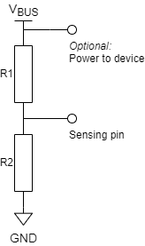
Use a resistor voltage divider that outputs (0.75 x Vdd) if VBUS is 4.4 V (see figure below).
Note
In either case, the voltage on the sensing pin must be logic low within 3 ms after the device is unplugged from the USB host.

Simple voltage divider for VBUS monitoring
To use this feature, in tinyusb_config_t, you must set self_powered to true and vbus_monitor_io to GPIO number that is used for VBUS monitoring.
USB Serial Device (CDC-ACM)
If the CDC option is enabled in Menuconfig, the USB Serial Device can be initialized with tusb_cdc_acm_init() according to the settings from tinyusb_config_cdcacm_t, see example below.
const tinyusb_config_cdcacm_t acm_cfg = {
    .usb_dev = TINYUSB_USBDEV_0,
    .cdc_port = TINYUSB_CDC_ACM_0,
    .rx_unread_buf_sz = 64,
    .callback_rx = NULL,
    .callback_rx_wanted_char = NULL,
    .callback_line_state_changed = NULL,
    .callback_line_coding_changed = NULL
};
tusb_cdc_acm_init(&acm_cfg);
To specify callbacks, you can either set the pointer to your tusb_cdcacm_callback_t function in the configuration structure or call tinyusb_cdcacm_register_callback() after initialization.
USB Serial Console
The USB Serial Device allows the redirection of all standard input/output streams (stdin, stdout, stderr) to USB. Thus, calling standard library input/output functions such as printf() will result into the data being sent/received over USB instead of UART.
Users should call esp_tusb_init_console() to switch the standard input/output streams to USB, and esp_tusb_deinit_console() to switch them back to UART.
USB Mass Storage Device (MSC)
If the MSC CONFIG_TINYUSB_MSC_ENABLED option is enabled in Menuconfig, the ESP Chip can be used as USB MSC Device. The storage media (SPI-Flash or SD-Card) can be initialized as shown below.
SPI-Flash
static esp_err_t storage_init_spiflash(wl_handle_t *wl_handle)
{
    ***
    esp_partition_t *data_partition = esp_partition_find_first(ESP_PARTITION_TYPE_DATA, ESP_PARTITION_SUBTYPE_DATA_FAT, NULL);
    ***
    wl_mount(data_partition, wl_handle);
    ***
}
storage_init_spiflash(&wl_handle);

const tinyusb_msc_spiflash_config_t config_spi = {
    .wl_handle = wl_handle
};
tinyusb_msc_storage_init_spiflash(&config_spi);
SD-Card
static esp_err_t storage_init_sdmmc(sdmmc_card_t **card)
{
    ***
    sdmmc_host_t host = SDMMC_HOST_DEFAULT();
    sdmmc_slot_config_t slot_config = SDMMC_SLOT_CONFIG_DEFAULT();
    // For SD Card, set bus width to use

    slot_config.width = 4;
    slot_config.clk = CONFIG_EXAMPLE_PIN_CLK;
    slot_config.cmd = CONFIG_EXAMPLE_PIN_CMD;
    slot_config.d0 = CONFIG_EXAMPLE_PIN_D0;
    slot_config.d1 = CONFIG_EXAMPLE_PIN_D1;
    slot_config.d2 = CONFIG_EXAMPLE_PIN_D2;
    slot_config.d3 = CONFIG_EXAMPLE_PIN_D3;
    slot_config.flags |= SDMMC_SLOT_FLAG_INTERNAL_PULLUP;

    sd_card = (sdmmc_card_t *)malloc(sizeof(sdmmc_card_t));
    (*host.init)();
    sdmmc_host_init_slot(host.slot, (const sdmmc_slot_config_t *) &slot_config);
    sdmmc_card_init(&host, sd_card);
    ***
}
storage_init_sdmmc(&card);

const tinyusb_msc_sdmmc_config_t config_sdmmc = {
    .card = card
};
tinyusb_msc_storage_init_sdmmc(&config_sdmmc);
MSC Performance Optimization
Single-Buffer Approach
The single-buffer approach improves performance by using a dedicated buffer to temporarily store incoming write data instead of processing it immediately in the callback.
Configurable buffer size: The buffer size is set via
CONFIG_TINYUSB_MSC_BUFSIZE, allowing users to balance performance and memory usage.
This approach ensures that USB transactions remain fast while avoiding potential delays caused by storage operations.
USB MSC Drive Performance
Note
SD card support is not available for ESP32-S2 in MSC device mode.
SPI Flash Performance:
FIFO Size |
Write Speed |
|---|---|
512 B |
5.59 KB/s |
8192 B |
21.54 KB/s |
Performance Limitations:
Internal SPI Flash performance is constrained by architectural limitations where program execution and storage access share the same flash chip. This results in program execution being suspended during flash writes, significantly impacting performance.
Internal SPI Flash usage is intended primarily for demonstration purposes. For practical use cases requiring higher performance, it is recommended to use external storage such as an SD card or an external SPI flash chip, where supported.
Application Examples
The examples can be found in the directory peripherals/usb/device.
peripherals/usb/device/tusb_console demonstrates how to set up ESP32-S2 to get log output via a Serial Device connection using the TinyUSB component, applicable for any Espressif boards that support USB-OTG.
peripherals/usb/device/tusb_serial_device demonstrates how to set up ESP32-S2 to function as a USB Serial Device using the TinyUSB component, with the ability to be configured as a double serial device.
peripherals/usb/device/tusb_midi demonstrates how to set up ESP32-S2 to function as a USB MIDI Device, outputting a MIDI note sequence via the native USB port using the TinyUSB component.
peripherals/usb/device/tusb_hid demonstrates how to implement a USB keyboard and mouse using the TinyUSB component, which sends 'key a/A pressed & released' events and moves the mouse in a square trajectory upon connection to a USB host.
peripherals/usb/device/tusb_msc demonstrates how to use the USB capabilities to create a Mass Storage Device that can be recognized by USB-hosts, allowing access to its internal data storage, with support for SPI Flash and SD MMC Card storage media.
peripherals/usb/device/tusb_composite_msc_serialdevice demonstrates how to set up ESP32-S2 to function simultaneously as both a USB Serial Device and an MSC device (SPI-Flash as the storage media) using the TinyUSB component.
peripherals/usb/device/tusb_ncm demonstrates how to transmit Wi-Fi data to a Linux or Windows host via USB using the Network Control Model (NCM), a sub-class of Communication Device Class (CDC) USB Device for Ethernet-over-USB applications, with the help of a TinyUSB component.