ESP32-C5
Note
This document is automatically translated using AI. Please excuse any detailed errors. The official English version is still in progress.
ESP32-C5 Chip/Module Startup Conditions
The operating voltage range of the ESP32-C5 chip is 3.0 V ~ 3.6 V; when using a single power supply, it is recommended that the power supply voltage for the ESP32-C5 series chip be 3.3 V, with a rated output current ideally at 600 mA or above.
The operating voltage range of the ESP32-C5 module is 3.0 V ~ 3.6 V; when using a single power supply, it is recommended that the power supply voltage for the ESP32-C5 series chip be 3.3 V, with a rated output current ideally at 600 mA or above.
- The CHIP_PU (EN) pin of ESP32-C5 is the chip’s boot pin. When CHIP_PU (EN) is at a high level, the chip is enabled; when it is at a low level, the chip is turned off. Note: The CHIP_PU pin should not be left floating. When ESP32-C5 is powered by a 3.3V system power supply, the CHIP_PU (EN) pin must be at a high level.
Hardware Wiring
The ESP32-C5 supports two firmware download methods: UART0 and USB.
When downloading firmware based on the ESP32-C5 Module, for
UART0, users need to prepare:3.3V Power Supply
Serial debugging tool
Dupont wire
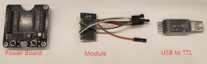
The ESP32-C5 uses UART0 to download firmware, supporting two download boot modes: Joint Download Boot 0 and Joint Download Boot 1. Different download boot modes have different level requirements for the Straping pin. The details are as follows:
In the Joint Download Boot 0 startup mode, the following wiring conditions need to be met to satisfy the hardware requirements for chip power supply, power-on startup, and entering download mode.
ESP32-C5
3.3V External Power Supply
Serial debugging tool
3V3
VDD
GND
GND
GND
EN
VDD
GPIO27 (pull-up, default is weak pull-up)
VDD
GPIO28 (pull down, default is high level)
GND
TXD0(GPIO11)
RXD
RXD0(GPIO12)
TXD
Note
In the Joint Download Boot 0 mode, when the chip is powered on, both
GPIO27andGPIO28cannot be at a low level at the same time.
In the Joint Download Boot 1 startup mode, the following wiring conditions need to be met to satisfy the hardware requirements for chip power supply, power-on startup, and entering download mode.
ESP32-C5
3.3V External Power Supply
Serial debugging tool
3V3
VDD
GND
GND
GND
EN
VDD
GPIO26 (pull-down, default is floating)
GND
GPIO27 (pull-down, default is weak pull-up)
GND
GPIO28 (pull-down, default is high level)
GND
TXD0(GPIO11)
RXD
RXD0(GPIO12)
TXD
Note
In the Joint Download Boot 1 startup mode, EFUSE_XTAL_48M_SEL_MODE needs to be 0;
Also, GPIO2 (i.e., MTMS) should be set to high level (48MHz) or low level (40MHz) depending on the size of the crystal used in the chip.
If EFUSE_XTAL_48M_SEL_MODE is 1, when using a 40MHz crystal, it requires EFUSE_XTAL_48M_SEL(0b000) to be an even number of 1s, and the level of GPIO2 (i.e., MTMS) is ignored.
If EFUSE_XTAL_48M_SEL_MODE is 1, when using a 48MHz crystal oscillator, it requires EFUSE_XTAL_48M_SEL(0b000) to be an odd number of 1s, the level of GPIO2 (i.e., MTMS) is ignored.
It is more recommended to use the Joint Download Boot 0 download startup mode.
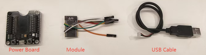
When downloading firmware based on the ESP32-C5 module, users need to prepare:
3.3V Power Supply
USB cable
Dupont wire
When using the
USBpin to download firmware, only the Joint Download Boot 0 boot mode is supported, and the following wiring conditions must be met:ESP32-C5
3.3V External Power Supply
USB cable
3V3
VDD
GND
GND
GND
EN
VDD
GPIO27 (pull-up, default is weak pull-up)
VDD
GPIO28 (pull down, default is high level)
GND
GPIO13
USB_D- (White)
GPIO14
USB_D+ (Green)
When testing with the ESP32-C5-DevKitC-1 Development Board, you can directly use a USB Type-C cable to connect the UART or USB interface on the development board for firmware download. If you are using the USB interface for firmware download for the first time, you need to manually pull down the GPIO28 pin, that is, hold down the Boot button and then power on, to manually enter the download mode.
Chip Power-On Startup Log
After powering on the ESP32-C5 chip/module, you can use the PC-side serial debugging software (such as XCOM) to view the UART0 serial output at chip power-on to confirm whether the chip has entered download mode. If the chip powers on and enters download mode, UART0 will print the following log:
ESP-ROM:esp32c5-eco2-20250121
Build:Jan 21 2025
rst:0x1 (POWERON),boot:0x8 (DOWNLOAD(UART0/USB))
waiting for download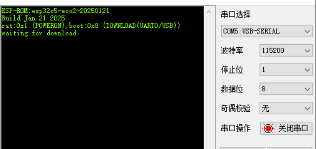
Note
After powering on the ESP32-C5 chip/module, if you do not see the log printing, you can trigger the log printing by pulling down and then pulling up the CHIP_PU (EN) pin to perform a hardware reset.
In addition, you can get the Strapping pins level state at power-on from the chip power-on startup log. For detailed instructions, please refer to ESP32-C5 Boot Log instructions.
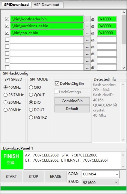
In terms of software, Espressif provides a PC-based Flash download tool, which can directly download firmware (.bin) into Flash. For usage instructions, refer to the Flash Download Tool User Guide.
After the firmware download is complete, if you want to run the burned firmware, you can pull up GPIO28 (default is high level) based on the above hardware wiring, and then pull down and pull up the CHIP_PU (EN) pin for hardware reset and restart, so that the chip re-enters the Flash boot mode. Finally, use the serial debugging software to view the UART0 log printout to check the firmware running status.