MCPWM
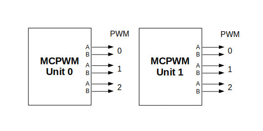
ESP32 has two MCPWM units which can be used to control different types of motors. Each unit has three pairs of PWM outputs.
MCPWM Overview
Further in documentation the outputs of a single unit are labeled PWMxA / PWMxB.
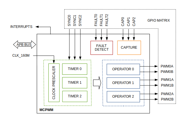
More detailed block diagram of the MCPWM unit is shown below. Each A/B pair may be clocked by any one of the three timers Timer 0, 1 and 2. The same timer may be used to clock more than one pair of PWM outputs. Each unit is also able to collect inputs such as SYNC SIGNALS, detect FAULT SIGNALS like motor overcurrent or overvoltage, as well as obtain feedback with CAPTURE SIGNALS on e.g. a rotor position.
MCPWM Block Diagram
Description of this API starts with configuration of MCPWM’s Timer and Generator submodules to provide the basic motor control functionality. Then it discusses more advanced submodules and functionalities of a Fault Handler, signal Capture, Carrier and Interrupts.
Contents
Configure a basic functionality of the outputs
Operate the outputs to drive a motor
Adjust how the motor is driven
Capture external signals to provide additional control over the outputs
Use Fault Handler to detect and manage faults
Add a higher frequency Carrier, if output signals are passed through an isolation transformer
Configuration and handling of Interrupts.
Configure
The scope of configuration depends on the motor type, in particular how many outputs and inputs are required, and what will be the sequence of signals to drive the motor.
In this case we will describe a simple configuration to control a brushed DC motor that is using only some of the available MCPWM’s resources. An example circuit is shown below. It includes a H-Bridge to switch polarization of a voltage applied to the motor (M) and to provide sufficient current to drive it.
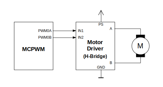
Example of Brushed DC Motor Control with MCPWM
Configuration covers the following steps:
Selection of a MPWn unit that will be used to drive the motor. There are two units available on-board of ESP32 and enumerated in
mcpwm_unit_t.Initialization of two GPIOs as output signals within selected unit by calling
mcpwm_gpio_init(). The two output signals are typically used to command the motor to rotate right or left. All available signal options are listed inmcpwm_io_signals_t. To set more than a single pin at a time, use functionmcpwm_set_pin()together withmcpwm_pin_config_t.Selection of a timer. There are three timers available within the unit. The timers are listed in
mcpwm_timer_t.Setting of the timer frequency and initial duty within
mcpwm_config_tstructure.Calling of
mcpwm_init()with the above parameters to make the configuration effective.
Operate
To operate a motor connected to the MCPWM unit, e.g. turn it left or right, or vary the speed, we should apply some control signals to the unit’s outputs. The outputs are organized into three pairs. Within a pair they are labeled “A” and “B” and each driven by a submodule called an “Generator”. To provide a PWM signal, the Operator itself, which contains two Generator, should be clocked by one of three available Timers. To make the API simpler, each Timer is automatically associated by the API to drive an Operator of the same index, e.g. Timer 0 is associated with Operator 0.
There are the following basic ways to control the outputs:
We can drive particular signal steady high or steady low with function
mcpwm_set_signal_high()ormcpwm_set_signal_low(). This will make the motor to turn with a maximum speed or stop. Depending on selected output A or B the motor will rotate either right or left.Another option is to drive the outputs with the PWM signal by calling
mcpwm_start()ormcpwm_stop(). The motor speed will be proportional to the PWM duty.To vary PWM’s duty call
mcpwm_set_duty()and provide the duty value in %. Optionally, you may callmcpwm_set_duty_in_us(), if you prefer to set the duty in microseconds. Checking of currently set value is possible by callingmcpwm_get_duty(). Phase of the PWM signal may be altered by callingmcpwm_set_duty_type(). The duty is set individually for each A and B output usingmcpwm_generator_tin specific function calls. The duty value refers either to high or low output signal duration. This is configured when callingmcpwm_init(), as discussed in section Configure, and selecting one of options frommcpwm_duty_type_t.
注解
Call function mcpwm_set_duty_type() every time after mcpwm_set_signal_high() or mcpwm_set_signal_low() to resume with previously set duty cycle.
Adjust
There are couple of ways to adjust a signal on the outputs and changing how the motor operates.
Set specific PWM frequency by calling
mcpwm_set_frequency(). This may be required to adjust to electrical or mechanical characteristics of particular motor and driver. To check what frequency is set, use functionmcpwm_get_frequency().Introduce a dead time between outputs A and B when they are changing the state to reverse direction of the motor rotation. This is to make up for on/off switching delay of the motor driver FETs. The dead time options are defined in
mcpwm_deadtime_type_tand enabled by callingmcpwm_deadtime_enable(). To disable this functionality callmcpwm_deadtime_disable().Synchronize outputs of operator submodules, e.g. to get raising edge of PWM0A/B and PWM1A/B to start exactly at the same time, or shift them between each other by a given phase. Synchronization is triggered by
SYNC SIGNALSshown on the block diagram of the MCPWM above, and defined inmcpwm_sync_signal_t. To attach the signal to a GPIO callmcpwm_gpio_init(). You can then enable synchronization with functionmcpwm_sync_enable(). As input parameters provide MCPWM unit, timer to synchronize, the synchronization signal and a phase to delay the timer.
注解
Synchronization signals are referred to using two different enumerations. First one mcpwm_io_signals_t is used together with function mcpwm_gpio_init() when selecting a GPIO as the signal input source. The second one mcpwm_sync_signal_t is used when enabling or disabling synchronization with mcpwm_sync_enable() or mcpwm_sync_disable().
Vary the pattern of the A/B output signals by getting MCPWM counters to count up, down and up/down (automatically changing the count direction). Respective configuration is done when calling
mcpwm_init(), as discussed in section Configure, and selecting one of counter types frommcpwm_counter_type_t. For explanation of how A/B PWM output signals are generated please refer to ESP32 Technical Reference Manual.
Capture
One of requirements of BLDC (Brushless DC, see figure below) motor control is sensing of the rotor position. To facilitate this task each MCPWM unit provides three sensing inputs together with dedicated hardware. The hardware is able to detect the input signal’s edge and measure time between signals. As result the control software is simpler and the CPU power may be used for other tasks.
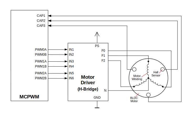
Example of Brushless DC Motor Control with MCPWM
The capture functionality may be used for other types of motors or tasks. The functionality is enabled in two steps:
Configuration of GPIOs to act as the capture signal inputs by calling functions
mcpwm_gpio_init()ormcpwm_set_pin(), that were described in section Configure.Enabling of the functionality itself by invoking
mcpwm_capture_enable(), selecting desired signal input frommcpwm_capture_signal_t, setting the signal edge withmcpwm_capture_on_edge_tand the signal count prescaler.
Within the second step above a 32-bit capture timer is enabled. The timer runs continuously driven by the APB clock. The clock frequency is typically 80 MHz. On each capture event the capture timer’s value is stored in time-stamp register that may be then checked by calling mcpwm_capture_signal_get_value(). The edge of the last signal may be checked with mcpwm_capture_signal_get_edge().
If not required anymore, the capture functionality may be disabled with mcpwm_capture_disable().
Fault Handler
Each unit of the MCPWM is able to sense external signals with information about failure of the motor, the motor driver or any other device connected to the MCPWM. There are three fault inputs per unit that may be routed to user selectable GPIOs. The MCPWM may be configured to perform one of four predefined actions on A/B outputs when a fault signal is received:
lock current state of the output
set the output low
set the output high
toggle the output
The user should determine possible failure modes of the motor and what action should be performed on detection of particular fault, e.g. drive all outputs low for a brushed motor, or lock current state for a stepper motor, etc. As result of this action the motor should be put into a safe state to reduce likelihood of a damage caused by the fault.
The fault handler functionality is enabled in two steps:
Configuration of GPIOs to act as fault signal inputs. This is done in analogous way as described for capture signals in section above. It includes setting the signal level to trigger the fault as defined in
mcpwm_fault_input_level_t.Initialization of the fault handler by calling either
mcpwm_fault_set_oneshot_mode()ormcpwm_fault_set_cyc_mode(). These functions set the mode that MCPWM should operate once fault signal becomes inactive. There are two modes possible:
State of MCPWM unit will be locked until reset -
mcpwm_fault_set_oneshot_mode().The MCPWM will resume operation once fault signal becoming inactive -
mcpwm_fault_set_cyc_mode().The function call parameters include selection of one of three fault inputs defined in
mcpwm_fault_signal_tand specific action on outputs A and B defined inmcpwm_action_on_pwmxa_tandmcpwm_action_on_pwmxb_t.
Particular fault signal may be disabled at the runtime by calling mcpwm_fault_deinit().
Carrier
The MCPWM has a carrier submodule used if galvanic isolation from the motor driver is required by passing the A/B output signals through transformers. Any of A and B output signals may be at 100% duty and not changing whenever motor is required to run steady at the full load. Coupling of non alternating signals with a transformer is problematic, so the signals are modulated by the carrier submodule to create an AC waveform, to make the coupling possible.
To use the carrier submodule, it should be first initialized by calling mcpwm_carrier_init(). The carrier parameters are defined in mcpwm_carrier_config_t structure invoked within the function call. Then the carrier functionality may be enabled by calling mcpwm_carrier_enable().
The carrier parameters may be then alerted at a runtime by calling dedicated functions to change individual fields of the mcpwm_carrier_config_t structure, like mcpwm_carrier_set_period(), mcpwm_carrier_set_duty_cycle(), mcpwm_carrier_output_invert(), etc.
This includes enabling and setting duration of the first pulse of the career with mcpwm_carrier_oneshot_mode_enable(). For more details please refer to “PWM Carrier Submodule” section of the ESP32 Technical Reference Manual.
To disable carrier functionality call mcpwm_carrier_disable().
Interrupts
Registering of the MCPWM interrupt handler is possible by calling mcpwm_isr_register().
Application Example
Examples of using MCPWM for motor control: peripherals/mcpwm:
Demonstration how to use each submodule of the MCPWM - peripherals/mcpwm/mcpwm_basic_config
Control of BLDC (brushless DC) motor with hall sensor feedback - peripherals/mcpwm/mcpwm_bldc_control
Brushed DC motor control - peripherals/mcpwm/mcpwm_brushed_dc_control
Servo motor control - peripherals/mcpwm/mcpwm_servo_control
API Reference
Header File
Enumerations
-
enum
mcpwm_intr_t¶ Interrupts for MCPWM.
Values:
-
MCPWM_LL_INTR_CAP0= BIT(27)¶ Capture 0 happened.
-
MCPWM_LL_INTR_CAP1= BIT(28)¶ Capture 1 happened.
-
MCPWM_LL_INTR_CAP2= BIT(29)¶ Capture 2 happened.
-
-
enum
mcpwm_counter_type_t¶ Select type of MCPWM counter.
Values:
-
MCPWM_UP_COUNTER= 1¶ For asymmetric MCPWM
-
MCPWM_DOWN_COUNTER¶ For asymmetric MCPWM
-
MCPWM_UP_DOWN_COUNTER¶ For symmetric MCPWM, frequency is half of MCPWM frequency set
-
MCPWM_COUNTER_MAX¶ Maximum counter mode
-
-
enum
mcpwm_duty_type_t¶ Select type of MCPWM duty cycle mode.
Values:
-
MCPWM_DUTY_MODE_0= 0¶ Active high duty, i.e. duty cycle proportional to high time for asymmetric MCPWM
-
MCPWM_DUTY_MODE_1¶ Active low duty, i.e. duty cycle proportional to low time for asymmetric MCPWM, out of phase(inverted) MCPWM
-
MCPWM_HAL_GENERATOR_MODE_FORCE_LOW
-
MCPWM_HAL_GENERATOR_MODE_FORCE_HIGH
-
MCPWM_DUTY_MODE_MAX¶ Num of duty cycle modes
-
-
enum
mcpwm_output_action_t¶ MCPWM select action to be taken on the output when event happens.
Values:
-
MCPWM_ACTION_NO_CHANGE= 0¶ No change in the output
-
MCPWM_ACTION_FORCE_LOW¶ Make output low
-
MCPWM_ACTION_FORCE_HIGH¶ Make output high
-
MCPWM_ACTION_TOGGLE¶ Make output toggle
-
-
enum
mcpwm_deadtime_type_t¶ MCPWM deadtime types, used to generate deadtime, RED refers to rising edge delay and FED refers to falling edge delay.
Values:
-
MCPWM_DEADTIME_BYPASS= 0¶ Bypass the deadtime
-
MCPWM_BYPASS_RED¶ MCPWMXA Out = MCPWMXA In with no delay, MCPWMXB Out = MCPWMXA In with falling edge delay
-
MCPWM_BYPASS_FED¶ MCPWMXA Out = MCPWMXA In with rising edge delay, MCPWMXB Out = MCPWMXB In with no delay
-
MCPWM_ACTIVE_HIGH_MODE¶ MCPWMXA Out = MCPWMXA In with rising edge delay, MCPWMXB Out = MCPWMXA In with falling edge delay
-
MCPWM_ACTIVE_LOW_MODE¶ MCPWMXA Out = MCPWMXA In with compliment of rising edge delay, MCPWMXB Out = MCPWMXA In with compliment of falling edge delay
-
MCPWM_ACTIVE_HIGH_COMPLIMENT_MODE¶ MCPWMXA Out = MCPWMXA In with rising edge delay, MCPWMXB = MCPWMXA In with compliment of falling edge delay
-
MCPWM_ACTIVE_LOW_COMPLIMENT_MODE¶ MCPWMXA Out = MCPWMXA In with compliment of rising edge delay, MCPWMXB Out = MCPWMXA In with falling edge delay
-
MCPWM_ACTIVE_RED_FED_FROM_PWMXA¶ MCPWMXA Out = MCPWMXB Out = MCPWMXA In with rising edge delay as well as falling edge delay
-
MCPWM_ACTIVE_RED_FED_FROM_PWMXB¶ MCPWMXA Out = MCPWMXB Out = MCPWMXB In with rising edge delay as well as falling edge delay
-
MCPWM_DEADTIME_TYPE_MAX
-
Header File
Functions
-
esp_err_t
mcpwm_gpio_init(mcpwm_unit_t mcpwm_num, mcpwm_io_signals_t io_signal, int gpio_num)¶ This function initializes each gpio signal for MCPWM.
- Note
This function initializes one gpio at a time.
- Return
ESP_OK Success
ESP_ERR_INVALID_ARG Parameter error
- Parameters
mcpwm_num: set MCPWM unit(0-1)io_signal: set MCPWM signals, each MCPWM unit has 6 output(MCPWMXA, MCPWMXB) and 9 input(SYNC_X, FAULT_X, CAP_X) ‘X’ is timer_num(0-2)gpio_num: set this to configure gpio for MCPWM, if you want to use gpio16, gpio_num = 16
-
esp_err_t
mcpwm_set_pin(mcpwm_unit_t mcpwm_num, const mcpwm_pin_config_t *mcpwm_pin)¶ Initialize MCPWM gpio structure.
- Note
This function can be used to initialize more then one gpio at a time.
- Return
ESP_OK Success
ESP_ERR_INVALID_ARG Parameter error
- Parameters
mcpwm_num: set MCPWM unit(0-1)mcpwm_pin: MCPWM pin structure
-
esp_err_t
mcpwm_init(mcpwm_unit_t mcpwm_num, mcpwm_timer_t timer_num, const mcpwm_config_t *mcpwm_conf)¶ Initialize MCPWM parameters.
- Return
ESP_OK Success
ESP_ERR_INVALID_ARG Parameter error
- Parameters
mcpwm_num: set MCPWM unit(0-1)timer_num: set timer number(0-2) of MCPWM, each MCPWM unit has 3 timers.mcpwm_conf: configure structure mcpwm_config_t
-
esp_err_t
mcpwm_set_frequency(mcpwm_unit_t mcpwm_num, mcpwm_timer_t timer_num, uint32_t frequency)¶ Set frequency(in Hz) of MCPWM timer.
- Return
ESP_OK Success
ESP_ERR_INVALID_ARG Parameter error
- Parameters
mcpwm_num: set MCPWM unit(0-1)timer_num: set timer number(0-2) of MCPWM, each MCPWM unit has 3 timersfrequency: set the frequency in Hz of each timer
-
esp_err_t
mcpwm_set_duty(mcpwm_unit_t mcpwm_num, mcpwm_timer_t timer_num, mcpwm_generator_t gen, float duty)¶ Set duty cycle of each operator(MCPWMXA/MCPWMXB)
- Return
ESP_OK Success
ESP_ERR_INVALID_ARG Parameter error
- Parameters
mcpwm_num: set MCPWM unit(0-1)timer_num: set timer number(0-2) of MCPWM, each MCPWM unit has 3 timersgen: set the generator(MCPWMXA/MCPWMXB), ‘X’ is operator number selectedduty: set duty cycle in %(i.e for 62.3% duty cycle, duty = 62.3) of each operator
-
esp_err_t
mcpwm_set_duty_in_us(mcpwm_unit_t mcpwm_num, mcpwm_timer_t timer_num, mcpwm_generator_t gen, uint32_t duty_in_us)¶ Set duty cycle of each operator(MCPWMXA/MCPWMXB) in us.
- Return
ESP_OK Success
ESP_ERR_INVALID_ARG Parameter error
- Parameters
mcpwm_num: set MCPWM unit(0-1)timer_num: set timer number(0-2) of MCPWM, each MCPWM unit has 3 timersgen: set the generator(MCPWMXA/MCPWMXB), ‘x’ is operator number selectedduty_in_us: set duty value in microseconds of each operator
-
esp_err_t
mcpwm_set_duty_type(mcpwm_unit_t mcpwm_num, mcpwm_timer_t timer_num, mcpwm_generator_t gen, mcpwm_duty_type_t duty_type)¶ Set duty either active high or active low(out of phase/inverted)
- Note
Call this function every time after mcpwm_set_signal_high or mcpwm_set_signal_low to resume with previously set duty cycle
- Return
ESP_OK Success
ESP_ERR_INVALID_ARG Parameter error
- Parameters
mcpwm_num: set MCPWM unit(0-1)timer_num: set timer number(0-2) of MCPWM, each MCPWM unit has 3 timersgen: set the generator(MCPWMXA/MCPWMXB), ‘x’ is operator number selectedduty_type: set active low or active high duty type
-
uint32_t
mcpwm_get_frequency(mcpwm_unit_t mcpwm_num, mcpwm_timer_t timer_num)¶ Get frequency of timer.
- Return
frequency of timer
- Parameters
mcpwm_num: set MCPWM unit(0-1)timer_num: set timer number(0-2) of MCPWM, each MCPWM unit has 3 timers
-
float
mcpwm_get_duty(mcpwm_unit_t mcpwm_num, mcpwm_timer_t timer_num, mcpwm_operator_t gen)¶ Get duty cycle of each operator.
- Return
duty cycle in % of each operator(56.7 means duty is 56.7%)
- Parameters
mcpwm_num: set MCPWM unit(0-1)timer_num: set timer number(0-2) of MCPWM, each MCPWM unit has 3 timersgen: set the generator(MCPWMXA/MCPWMXB), ‘x’ is operator number selected
-
esp_err_t
mcpwm_set_signal_high(mcpwm_unit_t mcpwm_num, mcpwm_timer_t timer_num, mcpwm_generator_t gen)¶ Use this function to set MCPWM signal high.
- Return
ESP_OK Success
ESP_ERR_INVALID_ARG Parameter error
- Parameters
mcpwm_num: set MCPWM unit(0-1)timer_num: set timer number(0-2) of MCPWM, each MCPWM unit has 3 timersgen: set the operator(MCPWMXA/MCPWMXB), ‘x’ is timer number selected
-
esp_err_t
mcpwm_set_signal_low(mcpwm_unit_t mcpwm_num, mcpwm_timer_t timer_num, mcpwm_generator_t gen)¶ Use this function to set MCPWM signal low.
- Return
ESP_OK Success
ESP_ERR_INVALID_ARG Parameter error
- Parameters
mcpwm_num: set MCPWM unit(0-1)timer_num: set timer number(0-2) of MCPWM, each MCPWM unit has 3 timersgen: set the operator(MCPWMXA/MCPWMXB), ‘x’ is timer number selected
-
esp_err_t
mcpwm_start(mcpwm_unit_t mcpwm_num, mcpwm_timer_t timer_num)¶ Start MCPWM signal on timer ‘x’.
- Return
ESP_OK Success
ESP_ERR_INVALID_ARG Parameter error
- Parameters
mcpwm_num: set MCPWM unit(0-1)timer_num: set timer number(0-2) of MCPWM, each MCPWM unit has 3 timers
-
esp_err_t
mcpwm_stop(mcpwm_unit_t mcpwm_num, mcpwm_timer_t timer_num)¶ Start MCPWM signal on timer ‘x’.
- Return
ESP_OK Success
ESP_ERR_INVALID_ARG Parameter error
- Parameters
mcpwm_num: set MCPWM unit(0-1)timer_num: set timer number(0-2) of MCPWM, each MCPWM unit has 3 timers
-
esp_err_t
mcpwm_carrier_init(mcpwm_unit_t mcpwm_num, mcpwm_timer_t timer_num, const mcpwm_carrier_config_t *carrier_conf)¶ Initialize carrier configuration.
- Return
ESP_OK Success
ESP_ERR_INVALID_ARG Parameter error
- Parameters
mcpwm_num: set MCPWM unit(0-1)timer_num: set timer number(0-2) of MCPWM, each MCPWM unit has 3 timerscarrier_conf: configure structure mcpwm_carrier_config_t
-
esp_err_t
mcpwm_carrier_enable(mcpwm_unit_t mcpwm_num, mcpwm_timer_t timer_num)¶ Enable MCPWM carrier submodule, for respective timer.
- Return
ESP_OK Success
ESP_ERR_INVALID_ARG Parameter error
- Parameters
mcpwm_num: set MCPWM unit(0-1)timer_num: set timer number(0-2) of MCPWM, each MCPWM unit has 3 timers
-
esp_err_t
mcpwm_carrier_disable(mcpwm_unit_t mcpwm_num, mcpwm_timer_t timer_num)¶ Disable MCPWM carrier submodule, for respective timer.
- Return
ESP_OK Success
ESP_ERR_INVALID_ARG Parameter error
- Parameters
mcpwm_num: set MCPWM unit(0-1)timer_num: set timer number(0-2) of MCPWM, each MCPWM unit has 3 timers
-
esp_err_t
mcpwm_carrier_set_period(mcpwm_unit_t mcpwm_num, mcpwm_timer_t timer_num, uint8_t carrier_period)¶ Set period of carrier.
- Return
ESP_OK Success
ESP_ERR_INVALID_ARG Parameter error
- Parameters
mcpwm_num: set MCPWM unit(0-1)timer_num: set timer number(0-2) of MCPWM, each MCPWM unit has 3 timerscarrier_period: set the carrier period of each timer, carrier period = (carrier_period + 1)*800ns (carrier_period <= 15)
-
esp_err_t
mcpwm_carrier_set_duty_cycle(mcpwm_unit_t mcpwm_num, mcpwm_timer_t timer_num, uint8_t carrier_duty)¶ Set duty_cycle of carrier.
- Return
ESP_OK Success
ESP_ERR_INVALID_ARG Parameter error
- Parameters
mcpwm_num: set MCPWM unit(0-1)timer_num: set timer number(0-2) of MCPWM, each MCPWM unit has 3 timerscarrier_duty: set duty_cycle of carrier , carrier duty cycle = carrier_duty*12.5% (chop_duty <= 7)
-
esp_err_t
mcpwm_carrier_oneshot_mode_enable(mcpwm_unit_t mcpwm_num, mcpwm_timer_t timer_num, uint8_t pulse_width)¶ Enable and set width of first pulse in carrier oneshot mode.
- Return
ESP_OK Success
ESP_ERR_INVALID_ARG Parameter error
- Parameters
mcpwm_num: set MCPWM unit(0-1)timer_num: set timer number(0-2) of MCPWM, each MCPWM unit has 3 timerspulse_width: set pulse width of first pulse in oneshot mode, width = (carrier period)*(pulse_width +1) (pulse_width <= 15)
-
esp_err_t
mcpwm_carrier_oneshot_mode_disable(mcpwm_unit_t mcpwm_num, mcpwm_timer_t timer_num)¶ Disable oneshot mode, width of first pulse = carrier period.
- Return
ESP_OK Success
ESP_ERR_INVALID_ARG Parameter error
- Parameters
mcpwm_num: set MCPWM unit(0-1)timer_num: set timer number(0-2) of MCPWM, each MCPWM unit has 3 timers
-
esp_err_t
mcpwm_carrier_output_invert(mcpwm_unit_t mcpwm_num, mcpwm_timer_t timer_num, mcpwm_carrier_out_ivt_t carrier_ivt_mode)¶ Enable or disable carrier output inversion.
- Return
ESP_OK Success
ESP_ERR_INVALID_ARG Parameter error
- Parameters
mcpwm_num: set MCPWM unit(0-1)timer_num: set timer number(0-2) of MCPWM, each MCPWM unit has 3 timerscarrier_ivt_mode: enable or disable carrier output inversion
-
esp_err_t
mcpwm_deadtime_enable(mcpwm_unit_t mcpwm_num, mcpwm_timer_t timer_num, mcpwm_deadtime_type_t dt_mode, uint32_t red, uint32_t fed)¶ Enable and initialize deadtime for each MCPWM timer.
- Return
ESP_OK Success
ESP_ERR_INVALID_ARG Parameter error
- Parameters
mcpwm_num: set MCPWM unit(0-1)timer_num: set timer number(0-2) of MCPWM, each MCPWM unit has 3 timersdt_mode: set deadtime modered: set rising edge delay = red*100nsfed: set rising edge delay = fed*100ns
-
esp_err_t
mcpwm_deadtime_disable(mcpwm_unit_t mcpwm_num, mcpwm_timer_t timer_num)¶ Disable deadtime on MCPWM timer.
- Return
ESP_OK Success
ESP_ERR_INVALID_ARG Parameter error
- Parameters
mcpwm_num: set MCPWM unit(0-1)timer_num: set timer number(0-2) of MCPWM, each MCPWM unit has 3 timers
-
esp_err_t
mcpwm_fault_init(mcpwm_unit_t mcpwm_num, mcpwm_fault_input_level_t intput_level, mcpwm_fault_signal_t fault_sig)¶ Initialize fault submodule, currently low level triggering is not supported.
- Return
ESP_OK Success
ESP_ERR_INVALID_ARG Parameter error
- Parameters
mcpwm_num: set MCPWM unit(0-1)intput_level: set fault signal level, which will cause fault to occurfault_sig: set the fault pin, which needs to be enabled
-
esp_err_t
mcpwm_fault_set_oneshot_mode(mcpwm_unit_t mcpwm_num, mcpwm_timer_t timer_num, mcpwm_fault_signal_t fault_sig, mcpwm_output_action_t action_on_pwmxa, mcpwm_output_action_t action_on_pwmxb)¶ Set oneshot mode on fault detection, once fault occur in oneshot mode reset is required to resume MCPWM signals.
- Note
currently low level triggering is not supported
- Return
ESP_OK Success
ESP_ERR_INVALID_ARG Parameter error
- Parameters
mcpwm_num: set MCPWM unit(0-1)timer_num: set timer number(0-2) of MCPWM, each MCPWM unit has 3 timersfault_sig: set the fault pin, which needs to be enabled for oneshot modeaction_on_pwmxa: action to be taken on MCPWMXA when fault occurs, either no change or high or low or toggleaction_on_pwmxb: action to be taken on MCPWMXB when fault occurs, either no change or high or low or toggle
-
esp_err_t
mcpwm_fault_set_cyc_mode(mcpwm_unit_t mcpwm_num, mcpwm_timer_t timer_num, mcpwm_fault_signal_t fault_sig, mcpwm_output_action_t action_on_pwmxa, mcpwm_output_action_t action_on_pwmxb)¶ Set cycle-by-cycle mode on fault detection, once fault occur in cyc mode MCPWM signal resumes as soon as fault signal becomes inactive.
- Note
currently low level triggering is not supported
- Return
ESP_OK Success
ESP_ERR_INVALID_ARG Parameter error
- Parameters
mcpwm_num: set MCPWM unit(0-1)timer_num: set timer number(0-2) of MCPWM, each MCPWM unit has 3 timersfault_sig: set the fault pin, which needs to be enabled for cyc modeaction_on_pwmxa: action to be taken on MCPWMXA when fault occurs, either no change or high or low or toggleaction_on_pwmxb: action to be taken on MCPWMXB when fault occurs, either no change or high or low or toggle
-
esp_err_t
mcpwm_fault_deinit(mcpwm_unit_t mcpwm_num, mcpwm_fault_signal_t fault_sig)¶ Disable fault signal.
- Return
ESP_OK Success
ESP_ERR_INVALID_ARG Parameter error
- Parameters
mcpwm_num: set MCPWM unit(0-1)fault_sig: fault pin, which needs to be disabled
-
esp_err_t
mcpwm_capture_enable(mcpwm_unit_t mcpwm_num, mcpwm_capture_signal_t cap_sig, mcpwm_capture_on_edge_t cap_edge, uint32_t num_of_pulse)¶ Initialize capture submodule.
- Return
ESP_OK Success
ESP_ERR_INVALID_ARG Parameter error
- Parameters
mcpwm_num: set MCPWM unit(0-1)cap_edge: set capture edge, BIT(0) - negative edge, BIT(1) - positive edgecap_sig: capture pin, which needs to be enablednum_of_pulse: count time between rising/falling edge between 2 *(pulses mentioned), counter uses APB_CLK
-
esp_err_t
mcpwm_capture_disable(mcpwm_unit_t mcpwm_num, mcpwm_capture_signal_t cap_sig)¶ Disable capture signal.
- Return
ESP_OK Success
ESP_ERR_INVALID_ARG Parameter error
- Parameters
mcpwm_num: set MCPWM unit(0-1)cap_sig: capture pin, which needs to be disabled
-
uint32_t
mcpwm_capture_signal_get_value(mcpwm_unit_t mcpwm_num, mcpwm_capture_signal_t cap_sig)¶ Get capture value.
- Return
Captured value
- Parameters
mcpwm_num: set MCPWM unit(0-1)cap_sig: capture pin on which value is to be measured
-
uint32_t
mcpwm_capture_signal_get_edge(mcpwm_unit_t mcpwm_num, mcpwm_capture_signal_t cap_sig)¶ Get edge of capture signal.
- Return
Capture signal edge: 1 - positive edge, 2 - negtive edge
- Parameters
mcpwm_num: set MCPWM unit(0-1)cap_sig: capture pin of whose edge is to be determined
-
esp_err_t
mcpwm_sync_enable(mcpwm_unit_t mcpwm_num, mcpwm_timer_t timer_num, mcpwm_sync_signal_t sync_sig, uint32_t phase_val)¶ Initialize sync submodule.
- Return
ESP_OK Success
ESP_ERR_INVALID_ARG Parameter error
- Parameters
mcpwm_num: set MCPWM unit(0-1)timer_num: set timer number(0-2) of MCPWM, each MCPWM unit has 3 timerssync_sig: set the synchronization pin, which needs to be enabledphase_val: phase value in 1/1000 (for 86.7%, phase_val = 867) which timer moves to on sync signal
-
esp_err_t
mcpwm_sync_disable(mcpwm_unit_t mcpwm_num, mcpwm_timer_t timer_num)¶ Disable sync submodule on given timer.
- Return
ESP_OK Success
ESP_ERR_INVALID_ARG Parameter error
- Parameters
mcpwm_num: set MCPWM unit(0-1)timer_num: set timer number(0-2) of MCPWM, each MCPWM unit has 3 timers
-
esp_err_t
mcpwm_isr_register(mcpwm_unit_t mcpwm_num, void (*fn)(void *), void *arg, int intr_alloc_flags, intr_handle_t *handle, )¶ Register MCPWM interrupt handler, the handler is an ISR. the handler will be attached to the same CPU core that this function is running on.
- Return
ESP_OK Success
ESP_ERR_INVALID_ARG Function pointer error.
- Parameters
mcpwm_num: set MCPWM unit(0-1)fn: interrupt handler function.arg: user-supplied argument passed to the handler function.intr_alloc_flags: flags used to allocate the interrupt. One or multiple (ORred) ESP_INTR_FLAG_* values. see esp_intr_alloc.h for more info.handle: pointer to return handle. If non-NULL, a handle for the interrupt will be returned here.
Structures
-
struct
mcpwm_pin_config_t¶ MCPWM pin number for.
Public Members
-
int
mcpwm0a_out_num¶ MCPWM0A out pin
-
int
mcpwm0b_out_num¶ MCPWM0A out pin
-
int
mcpwm1a_out_num¶ MCPWM0A out pin
-
int
mcpwm1b_out_num¶ MCPWM0A out pin
-
int
mcpwm2a_out_num¶ MCPWM0A out pin
-
int
mcpwm2b_out_num¶ MCPWM0A out pin
-
int
mcpwm_sync0_in_num¶ SYNC0 in pin
-
int
mcpwm_sync1_in_num¶ SYNC1 in pin
-
int
mcpwm_sync2_in_num¶ SYNC2 in pin
-
int
mcpwm_fault0_in_num¶ FAULT0 in pin
-
int
mcpwm_fault1_in_num¶ FAULT1 in pin
-
int
mcpwm_fault2_in_num¶ FAULT2 in pin
-
int
mcpwm_cap0_in_num¶ CAP0 in pin
-
int
mcpwm_cap1_in_num¶ CAP1 in pin
-
int
mcpwm_cap2_in_num¶ CAP2 in pin
-
int
-
struct
mcpwm_config_t¶ MCPWM config structure.
Public Members
-
uint32_t
frequency¶ Set frequency of MCPWM in Hz
-
float
cmpr_a¶ Set % duty cycle for operator a(MCPWMXA), i.e for 62.3% duty cycle, duty_a = 62.3
-
float
cmpr_b¶ Set % duty cycle for operator b(MCPWMXB), i.e for 48% duty cycle, duty_b = 48.0
-
mcpwm_duty_type_t
duty_mode¶ Set type of duty cycle
-
mcpwm_counter_type_t
counter_mode¶ Set type of MCPWM counter
-
uint32_t
-
struct
mcpwm_carrier_config_t¶ MCPWM config carrier structure.
Public Members
-
uint8_t
carrier_period¶ Set carrier period = (carrier_period + 1)*800ns, carrier_period should be < 16
-
uint8_t
carrier_duty¶ Set carrier duty cycle, carrier_duty should be less than 8 (increment every 12.5%)
-
uint8_t
pulse_width_in_os¶ Set pulse width of first pulse in one shot mode = (carrier period)*(pulse_width_in_os + 1), should be less then 16
-
mcpwm_carrier_os_t
carrier_os_mode¶ Enable or disable carrier oneshot mode
-
mcpwm_carrier_out_ivt_t
carrier_ivt_mode¶ Invert output of carrier
-
uint8_t
Macros
-
MCPWM_OPR_A
-
MCPWM_OPR_B
-
MCPWM_OPR_MAX
-
MCPWM_NO_CHANGE_IN_MCPWMXA
-
MCPWM_FORCE_MCPWMXA_LOW
-
MCPWM_FORCE_MCPWMXA_HIGH
-
MCPWM_TOG_MCPWMXA
-
MCPWM_NO_CHANGE_IN_MCPWMXB
-
MCPWM_FORCE_MCPWMXB_LOW
-
MCPWM_FORCE_MCPWMXB_HIGH
-
MCPWM_TOG_MCPWMXB
Type Definitions
-
typedef mcpwm_generator_t
mcpwm_operator_t
-
typedef mcpwm_output_action_t
mcpwm_action_on_pwmxa_t
-
typedef mcpwm_output_action_t
mcpwm_action_on_pwmxb_t
Enumerations
-
enum
mcpwm_io_signals_t¶ IO signals for the MCPWM.
6 MCPWM output pins that generate PWM signals
3 MCPWM fault input pins to detect faults like overcurrent, overvoltage, etc.
3 MCPWM sync input pins to synchronize MCPWM outputs signals
3 MCPWM capture input pins to gather feedback from controlled motors, using e.g. hall sensors
Values:
-
MCPWM0A= 0¶ PWM0A output pin
-
MCPWM0B¶ PWM0B output pin
-
MCPWM1A¶ PWM1A output pin
-
MCPWM1B¶ PWM1B output pin
-
MCPWM2A¶ PWM2A output pin
-
MCPWM2B¶ PWM2B output pin
-
MCPWM_SYNC_0¶ SYNC0 input pin
-
MCPWM_SYNC_1¶ SYNC1 input pin
-
MCPWM_SYNC_2¶ SYNC2 input pin
-
MCPWM_FAULT_0¶ FAULT0 input pin
-
MCPWM_FAULT_1¶ FAULT1 input pin
-
MCPWM_FAULT_2¶ FAULT2 input pin
-
MCPWM_CAP_0= 84¶ CAP0 input pin
-
MCPWM_CAP_1¶ CAP1 input pin
-
MCPWM_CAP_2¶ CAP2 input pin
-
enum
mcpwm_unit_t¶ Select MCPWM unit.
Values:
-
MCPWM_UNIT_0= 0¶ MCPWM unit0 selected
-
MCPWM_UNIT_1¶ MCPWM unit1 selected
-
MCPWM_UNIT_MAX¶ Num of MCPWM units on ESP32
-
-
enum
mcpwm_timer_t¶ Select MCPWM timer.
Values:
-
MCPWM_TIMER_0= 0¶ Select MCPWM timer0
-
MCPWM_TIMER_1¶ Select MCPWM timer1
-
MCPWM_TIMER_2¶ Select MCPWM timer2
-
MCPWM_TIMER_MAX¶ Num of MCPWM timers on ESP32
-
-
enum
mcpwm_generator_t¶ Select MCPWM operator.
Values:
-
MCPWM_GEN_A= 0¶ Select MCPWMXA, where ‘X’ is operator number
-
MCPWM_GEN_B¶ Select MCPWMXB, where ‘X’ is operator number
-
MCPWM_GEN_MAX¶ Num of generators to each operator of MCPWM
-
-
enum
mcpwm_carrier_os_t¶ MCPWM carrier oneshot mode, in this mode the width of the first pulse of carrier can be programmed.
Values:
-
MCPWM_ONESHOT_MODE_DIS= 0¶ Enable oneshot mode
-
MCPWM_ONESHOT_MODE_EN¶ Disable oneshot mode
-
-
enum
mcpwm_carrier_out_ivt_t¶ MCPWM carrier output inversion, high frequency carrier signal active with MCPWM signal is high.
Values:
-
MCPWM_CARRIER_OUT_IVT_DIS= 0¶ Enable carrier output inversion
-
MCPWM_CARRIER_OUT_IVT_EN¶ Disable carrier output inversion
-
-
enum
mcpwm_fault_signal_t¶ MCPWM select fault signal input.
Values:
-
MCPWM_SELECT_F0= 0¶ Select F0 as input
-
MCPWM_SELECT_F1¶ Select F1 as input
-
MCPWM_SELECT_F2¶ Select F2 as input
-