SPI Slave Driver
SPI Slave driver is a program that controls ESP32’s SPI peripherals while they function as slaves.
Overview of ESP32’s SPI peripherals
ESP32 integrates two general purpose SPI controllers which can be used as slave nodes driven by an off-chip SPI master
SPI2, sometimes referred to as HSPI
SPI3, sometimes referred to as VSPI
SPI2 and SPI3 have independent signal buses with the same respective names.
Terminology
The terms used in relation to the SPI slave driver are given in the table below.
Term |
Definition |
|---|---|
Host |
The SPI controller peripheral external to ESP32 that initiates SPI transmissions over the bus, and acts as an SPI Master. |
Device |
SPI slave device, in this case the SPI2 and SPI3 controllers. Each Device shares the MOSI, MISO and SCLK signals but is only active on the bus when the Host asserts the Device’s individual CS line. |
Bus |
A signal bus, common to all Devices connected to one Host. In general, a bus includes the following lines: MISO, MOSI, SCLK, one or more CS lines, and, optionally, QUADWP and QUADHD. So Devices are connected to the same lines, with the exception that each Device has its own CS line. Several Devices can also share one CS line if connected in the daisy-chain manner. |
|
Master In, Slave Out, a.k.a. Q. Data transmission from a Device to Host. |
|
Master Out, Slave in, a.k.a. D. Data transmission from a Host to Device. |
|
Serial Clock. Oscillating signal generated by a Host that keeps the transmission of data bits in sync. |
|
Chip Select. Allows a Host to select individual Device(s) connected to the bus in order to send or receive data. |
|
Write Protect signal. Only used for 4-bit (qio/qout) transactions. |
|
Hold signal. Only used for 4-bit (qio/qout) transactions. |
|
The action of activating a line. The opposite action of returning the line back to inactive (back to idle) is called de-assertion. |
Transaction |
One instance of a Host asserting a CS line, transferring data to and from a Device, and de-asserting the CS line. Transactions are atomic, which means they can never be interrupted by another transaction. |
Launch edge |
Edge of the clock at which the source register launches the signal onto the line. |
Latch edge |
Edge of the clock at which the destination register latches in the signal. |
Driver Features
The SPI slave driver allows using the SPI2 and/or SPI3 peripherals as full-duplex Devices. The driver can send/receive transactions up to 64 bytes in length, or utilize DMA to send/receive longer transactions. However, there are some known issues related to DMA.
SPI Transactions
A full-duplex SPI transaction begins when the Host asserts the CS line and starts sending out clock pulses on the SCLK line. Every clock pulse, a data bit is shifted from the Host to the Device on the MOSI line and back on the MISO line at the same time. At the end of the transaction, the Host de-asserts the CS line.
The attributes of a transaction are determined by the configuration structure for an SPI host acting as a slave device spi_slave_interface_config_t, and transaction configuration structure spi_slave_transaction_t.
As not every transaction requires both writing and reading data, you have a choice to configure the spi_transaction_t structure for TX only, RX only, or TX and RX transactions. If spi_slave_transaction_t::rx_buffer is set to NULL, the read phase will be skipped. If spi_slave_transaction_t::tx_buffer is set to NULL, the write phase will be skipped.
注解
A Host should not start a transaction before its Device is ready for receiving data. It is recommended to use another GPIO pin for a handshake signal to sync the Devices. For more details, see Transaction Interval.
Driver Usage
Initialize an SPI peripheral as a Device by calling the function cpp:func:spi_slave_initialize. Make sure to set the correct I/O pins in the struct
bus_config. Set the unused signals to-1.
If transactions will be longer than 32 bytes, allow a DMA channel 1 or 2 by setting the parameter dma_chan to 1 or 2 respectively. Otherwise, set dma_chan to 0.
Before initiating transactions, fill one or more
spi_slave_transaction_tstructs with the transaction parameters required. Either queue all transactions by calling the functionspi_slave_queue_trans()and, at a later time, query the result by using the functionspi_slave_get_trans_result(), or handle all requests individually by feeding them intospi_slave_transmit(). The latter two functions will be blocked until the Host has initiated and finished a transaction, causing the queued data to be sent and received.(Optional) To unload the SPI slave driver, call
spi_slave_free().
Transaction Data and Master/Slave Length Mismatches
Normally, the data that needs to be transferred to or from a Device is read or written to a chunk of memory indicated by the rx_buffer and tx_buffer members of the spi_transaction_t structure. The SPI driver can be configured to use DMA for transfers, in which case these buffers must be allocated in DMA-capable memory using pvPortMallocCaps(size, MALLOC_CAP_DMA).
The amount of data that the driver can read or write to the buffers is limited by the member spi_transaction_t::length. However, this member does not define the actual length of an SPI transaction. A transaction’s length is determined by a Host which drives the clock and CS lines. The actual length of the transmission can be read only after a transaction is finished from the member spi_slave_transaction_t::trans_len.
If the length of the transmission is greater than the buffer length, only the initial number of bits specified in the length member will be sent and received. In this case, trans_len is set to length instead of the actual transaction length. To meet the actual transaction length requirements, set length to a value greater than the maximum trans_len expected. If the transmission length is shorter than the buffer length, only the data equal to the length of the buffer will be transmitted.
警告
The ESP32 DMA hardware has a limit to the number of bytes sent by a Host and received by a Device. The transaction length must be longer than 8 bytes and a multiple of 4 bytes; otherwise, the SPI hardware might fail to receive the last 1 to 7 bytes.
GPIO Matrix and IO_MUX
Most of ESP32’s peripheral signals have direct connection to their dedicated IO_MUX pins. However, the signals can also be routed to any other available pins using the less direct GPIO matrix.
If at least one signal is routed through the GPIO matrix, then all signals will be routed through it. The GPIO matrix samples all signals at 80 MHz and transmits them between the GPIO and the peripheral.
If the driver is configured so that all SPI signals are either routed to their dedicated IO_MUX pins or are not connected at all, the GPIO matrix will be bypassed.
The GPIO matrix introduces flexibility of routing but also increases the input delay of the MISO signal, which makes MISO setup time violations more likely. If SPI needs to operate at high speeds, use dedicated IO_MUX pins.
注解
For more details about the influence of the MISO input delay on the maximum clock frequency, see Timing Considerations.
The IO_MUX pins for SPI buses are given below.
Pin Name |
SPI2 |
SPI3 |
|---|---|---|
GPIO Number |
||
CS0* |
15 |
5 |
SCLK |
14 |
18 |
MISO |
12 |
19 |
MOSI |
13 |
23 |
QUADWP |
2 |
22 |
QUADHD |
4 |
21 |
Only the first Device attached to the bus can use the CS0 pin.
Speed and Timing Considerations
Transaction Interval
The ESP32 SPI slave peripherals are designed as general purpose Devices controlled by a CPU. As opposed to dedicated slaves, CPU-based SPI Devices have a limited number of pre-defined registers. All transactions must be handled by the CPU, which means that the transfers and responses are not real-time, and there might be noticeable latency.
As a solution, a Device’s response rate can be doubled by using the functions spi_slave_queue_trans() and then spi_slave_get_trans_result() instead of using spi_slave_transmit().
You can also configure a GPIO pin through which the Device will signal to the Host when it is ready for a new transaction. A code example of this can be found in peripherals/spi_slave.
SCLK Frequency Requirements
The SPI slaves are designed to operate at up to 10 MHz. The data cannot be recognized or received correctly if the clock is too fast or does not have a 50% duty cycle.
On top of that, there are additional requirements for the data to meet the timing constraints:
- Read (MOSI):
The Device can read data correctly only if the data is already set at the launch edge. Although it is usually the case for most masters.
- Write (MISO):
The output delay of the MISO signal needs to be shorter than half of a clock cycle period so that the MISO line is stable before the next latch edge. Given that the clock is balanced, the output delay and frequency limitations in different cases are given below.
Output delay of MISO (ns)
Freq. limit (MHz)
IO_MUX
43.75
<11.4
GPIO matrix
68.75
<7.2
- Note:
If the frequency is equal to the limitation, it can lead to random errors.
The clock uncertainty between Host and Device (12.5ns) is included.
The output delay is measured under ideal circumstances (no load). If the MISO pin is heavily loaded, the output delay will be longer, and the maximum allowed frequency will be lower.
Exception: The frequency is allowed to be higher if the master has more tolerance for the MISO setup time, e.g., latch data at the next edge than expected, or configurable latching time.
Restrictions and Known Issues
If DMA is enabled, the rx buffer should be word-aligned (starting from a 32-bit boundary and having a length of multiples of 4 bytes). Otherwise, DMA may write incorrectly or not in a boundary aligned manner. The driver reports an error if this condition is not satisfied.
Also, a Host should write lengths that are multiples of 4 bytes. The data with inappropriate lengths will be discarded.
Furthermore, DMA requires SPI modes 1 and 3. For SPI modes 0 and 2, the MISO signal has to be launched half a clock cycle earlier to meet the timing. The new timing is as follows:
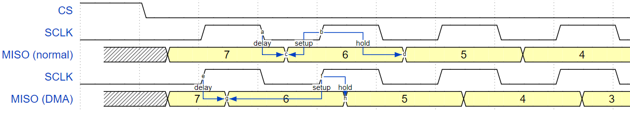
If DMA is enabled, a Device’s launch edge is half of an SPI clock cycle ahead of the normal time, shifting to the Master’s actual latch edge. In this case, if the GPIO matrix is bypassed, the hold time for data sampling is 68.75 ns and no longer a half of an SPI clock cycle. If the GPIO matrix is used, the hold time will increase to 93.75 ns. The Host should sample the data immediately at the latch edge or communicate in SPI modes 1 or 3. If your Host cannot meet these timing requirements, initialize your Device without DMA.
Application Example
The code example for Device/Host communication can be found in the peripherals/spi_slave directory of ESP-IDF examples.
API Reference
Header File
Functions
-
esp_err_t
spi_slave_initialize(spi_host_device_t host, const spi_bus_config_t *bus_config, const spi_slave_interface_config_t *slave_config, int dma_chan)¶ Initialize a SPI bus as a slave interface.
- Warning
For now, only supports HSPI and VSPI.
- Warning
If a DMA channel is selected, any transmit and receive buffer used should be allocated in DMA-capable memory.
- Warning
The ISR of SPI is always executed on the core which calls this function. Never starve the ISR on this core or the SPI transactions will not be handled.
- Return
ESP_ERR_INVALID_ARG if configuration is invalid
ESP_ERR_INVALID_STATE if host already is in use
ESP_ERR_NO_MEM if out of memory
ESP_OK on success
- Parameters
host: SPI peripheral to use as a SPI slave interfacebus_config: Pointer to a spi_bus_config_t struct specifying how the host should be initializedslave_config: Pointer to a spi_slave_interface_config_t struct specifying the details for the slave interfacedma_chan: Either 1 or 2. A SPI bus used by this driver must have a DMA channel associated with it. The SPI hardware has two DMA channels to share. This parameter indicates which one to use.
-
esp_err_t
spi_slave_free(spi_host_device_t host)¶ Free a SPI bus claimed as a SPI slave interface.
- Return
ESP_ERR_INVALID_ARG if parameter is invalid
ESP_ERR_INVALID_STATE if not all devices on the bus are freed
ESP_OK on success
- Parameters
host: SPI peripheral to free
-
esp_err_t
spi_slave_queue_trans(spi_host_device_t host, const spi_slave_transaction_t *trans_desc, TickType_t ticks_to_wait)¶ Queue a SPI transaction for execution.
Queues a SPI transaction to be executed by this slave device. (The transaction queue size was specified when the slave device was initialised via spi_slave_initialize.) This function may block if the queue is full (depending on the ticks_to_wait parameter). No SPI operation is directly initiated by this function, the next queued transaction will happen when the master initiates a SPI transaction by pulling down CS and sending out clock signals.
This function hands over ownership of the buffers in
trans_descto the SPI slave driver; the application is not to access this memory untilspi_slave_queue_transis called to hand ownership back to the application.- Return
ESP_ERR_INVALID_ARG if parameter is invalid
ESP_OK on success
- Parameters
host: SPI peripheral that is acting as a slavetrans_desc: Description of transaction to execute. Not const because we may want to write status back into the transaction description.ticks_to_wait: Ticks to wait until there’s room in the queue; use portMAX_DELAY to never time out.
-
esp_err_t
spi_slave_get_trans_result(spi_host_device_t host, spi_slave_transaction_t **trans_desc, TickType_t ticks_to_wait)¶ Get the result of a SPI transaction queued earlier.
This routine will wait until a transaction to the given device (queued earlier with spi_slave_queue_trans) has succesfully completed. It will then return the description of the completed transaction so software can inspect the result and e.g. free the memory or re-use the buffers.
It is mandatory to eventually use this function for any transaction queued by
spi_slave_queue_trans.- Return
ESP_ERR_INVALID_ARG if parameter is invalid
ESP_OK on success
- Parameters
host: SPI peripheral to that is acting as a slave[out] trans_desc: Pointer to variable able to contain a pointer to the description of the transaction that is executedticks_to_wait: Ticks to wait until there’s a returned item; use portMAX_DELAY to never time out.
-
esp_err_t
spi_slave_transmit(spi_host_device_t host, spi_slave_transaction_t *trans_desc, TickType_t ticks_to_wait)¶ Do a SPI transaction.
Essentially does the same as spi_slave_queue_trans followed by spi_slave_get_trans_result. Do not use this when there is still a transaction queued that hasn’t been finalized using spi_slave_get_trans_result.
- Return
ESP_ERR_INVALID_ARG if parameter is invalid
ESP_OK on success
- Parameters
host: SPI peripheral to that is acting as a slavetrans_desc: Pointer to variable able to contain a pointer to the description of the transaction that is executed. Not const because we may want to write status back into the transaction description.ticks_to_wait: Ticks to wait until there’s a returned item; use portMAX_DELAY to never time out.
Structures
-
struct
spi_slave_interface_config_t¶ This is a configuration for a SPI host acting as a slave device.
Public Members
-
int
spics_io_num¶ CS GPIO pin for this device.
-
uint32_t
flags¶ Bitwise OR of SPI_SLAVE_* flags.
-
int
queue_size¶ Transaction queue size. This sets how many transactions can be ‘in the air’ (queued using spi_slave_queue_trans but not yet finished using spi_slave_get_trans_result) at the same time.
-
uint8_t
mode¶ SPI mode (0-3)
-
slave_transaction_cb_t
post_setup_cb¶ Callback called after the SPI registers are loaded with new data.
This callback is called within interrupt context should be in IRAM for best performance, see “Transferring Speed” section in the SPI Master documentation for full details. If not, the callback may crash during flash operation when the driver is initialized with ESP_INTR_FLAG_IRAM.
-
slave_transaction_cb_t
post_trans_cb¶ Callback called after a transaction is done.
This callback is called within interrupt context should be in IRAM for best performance, see “Transferring Speed” section in the SPI Master documentation for full details. If not, the callback may crash during flash operation when the driver is initialized with ESP_INTR_FLAG_IRAM.
-
int
-
struct
spi_slave_transaction_t¶ This structure describes one SPI transaction
Public Members
-
size_t
length¶ Total data length, in bits.
-
size_t
trans_len¶ Transaction data length, in bits.
-
const void *
tx_buffer¶ Pointer to transmit buffer, or NULL for no MOSI phase.
-
void *
rx_buffer¶ Pointer to receive buffer, or NULL for no MISO phase. When the DMA is anabled, must start at WORD boundary (
rx_buffer%4==0), and has length of a multiple of 4 bytes.
-
void *
user¶ User-defined variable. Can be used to store eg transaction ID.
-
size_t
Macros
-
SPI_SLAVE_TXBIT_LSBFIRST¶ Transmit command/address/data LSB first instead of the default MSB first.
-
SPI_SLAVE_RXBIT_LSBFIRST¶ Receive data LSB first instead of the default MSB first.
-
SPI_SLAVE_BIT_LSBFIRST¶ Transmit and receive LSB first.
Type Definitions
-
typedef struct spi_slave_transaction_t
spi_slave_transaction_t
-
typedef void (*
slave_transaction_cb_t)(spi_slave_transaction_t *trans)