RMT
The RMT (Remote Control) module driver can be used to send and receive infrared remote control signals. Due to flexibility of RMT module, the driver can also be used to generate or receive many other types of signals.
The signal, which consists of a series of pulses, is generated by RMT’s transmitter based on a list of values. The values define the pulse duration and a binary level, see below. The transmitter can also provide a carrier and modulate it with provided pulses.
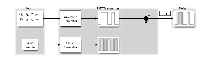
RMT Transmitter Overview
The reverse operation is performed by the receiver, where a series of pulses is decoded into a list of values containing the pulse duration and binary level. A filter may be applied to remove high frequency noise from the input signal.

RMT Receiver Overview
There couple of typical steps to setup and operate the RMT and they are discussed in the following sections:
The RMT has eight channels numbered from zero to seven. Each channel is able to independently transmit or receive data. They are referred to using indexes defined in structure rmt_channel_t.
Configure Driver
There are several parameters that define how particular channel operates. Most of these parameters are configured by setting specific members of rmt_config_t structure. Some of the parameters are common to both transmit or receive mode, and some are mode specific. They are all discussed below.
Common Parameters
The channel to be configured, select one from the
rmt_channel_tenumerator.The RMT operation mode - whether this channel is used to transmit or receive data, selected by setting a rmt_mode members to one of the values from
rmt_mode_t.What is the pin number to transmit or receive RMT signals, selected by setting gpio_num.
How many memory blocks will be used by the channel, set with mem_block_num.
Extra miscellaneous parameters for the channel can be set in the flags.
When RMT_CHANNEL_FLAGS_ALWAYS_ON is set, RMT channel will take REF_TICK as source clock. The benefit is, RMT channel can continue work even when APB clock is changing. See power_management for more information.
A clock divider, that will determine the range of pulse length generated by the RMT transmitter or discriminated by the receiver. Selected by setting clk_div to a value within [1 .. 255] range. The RMT source clock is typically APB CLK, 80Mhz by default. But when RMT_CHANNEL_FLAGS_ALWAYS_ON is set in flags, RMT source clock is changed to REF_TICK.
注解
The period of a square wave after the clock divider is called a ‘tick’. The length of the pulses generated by the RMT transmitter or discriminated by the receiver is configured in number of ‘ticks’.
There are also couple of specific parameters that should be set up depending if selected channel is configured in Transmit Mode or Receive Mode:
Transmit Mode
When configuring channel in transmit mode, set tx_config and the following members of rmt_tx_config_t:
Transmit the currently configured data items in a loop - loop_en
Enable the RMT carrier signal - carrier_en
Frequency of the carrier in Hz - carrier_freq_hz
Duty cycle of the carrier signal in percent (%) - carrier_duty_percent
Level of the RMT output, when the carrier is applied - carrier_level
Enable the RMT output if idle - idle_output_en
Set the signal level on the RMT output if idle - idle_level
Receive Mode
In receive mode, set rx_config and the following members of rmt_rx_config_t:
Enable a filter on the input of the RMT receiver - filter_en
A threshold of the filter, set in the number of ticks - filter_ticks_thresh. Pulses shorter than this setting will be filtered out. Note, that the range of entered tick values is [0..255].
A pulse length threshold that will turn the RMT receiver idle, set in number of ticks - idle_threshold. The receiver will ignore pulses longer than this setting.
Finalize Configuration
Once the rmt_config_t structure is populated with parameters, it should be then invoked with rmt_config() to make the configuration effective.
The last configuration step is installation of the driver in memory by calling rmt_driver_install(). If rx_buf_size parameter of this function is > 0, then a ring buffer for incoming data will be allocated. A default ISR handler will be installed, see a note in Use Interrupts.
Now, depending on how the channel is configured, we are ready to either Transmit Data or Receive Data. This is described in next two sections.
Transmit Data
Before being able to transmit some RMT pulses, we need to define the pulse pattern. The minimum pattern recognized by the RMT controller, later called an ‘item’, is provided in a structure rmt_item32_t. Each item consists of two pairs of two values. The first value in a pair describes the signal duration in ticks and is 15 bits long, the second provides the signal level (high or low) and is contained in a single bit. A block of couple of items and the structure of an item is presented below.
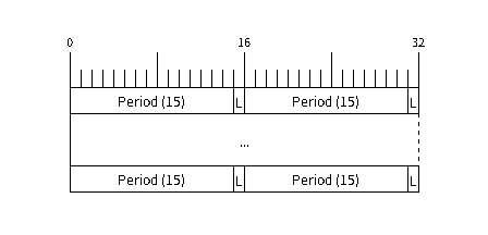
Structure of RMT items (L - signal level)
For a simple example how to define a block of items see peripherals/rmt/morse_code.
The items are provided to the RMT controller by calling function rmt_write_items(). This function also automatically triggers start of transmission. It may be called to wait for transmission completion or exit just after transmission start. In such case you can wait for the transmission end by calling rmt_wait_tx_done(). This function does not limit the number of data items to transmit. It is using an interrupt to successively copy the new data chunks to RMT’s internal memory as previously provided data are sent out.
Another way to provide data for transmission is by calling rmt_fill_tx_items(). In this case transmission is not started automatically. To control the transmission process use rmt_tx_start() and rmt_tx_stop(). The number of items to sent is restricted by the size of memory blocks allocated in the RMT controller’s internal memory, see rmt_set_mem_block_num().
Receive Data
Before starting the receiver we need some storage for incoming items. The RMT controller has 512 x 32-bits of internal RAM shared between all eight channels.
In typical scenarios it is not enough as an ultimate storage for all incoming (and outgoing) items. Therefore this API supports retrieval of incoming items on the fly to save them in a ring buffer of a size defined by the user. The size is provided when calling rmt_driver_install() discussed above. To get a handle to this buffer call rmt_get_ringbuf_handle().
With the above steps complete we can start the receiver by calling rmt_rx_start() and then move to checking what’s inside the buffer. To do so, you can use common FreeRTOS functions that interact with the ring buffer. Please see an example how to do it in peripherals/rmt/ir_protocols.
To stop the receiver, call rmt_rx_stop().
Change Operation Parameters
Previously described function rmt_config() provides a convenient way to set several configuration parameters in one shot. This is usually done on application start. Then, when the application is running, the API provides an alternate way to update individual parameters by calling dedicated functions. Each function refers to the specific RMT channel provided as the first input parameter. Most of the functions have _get_ counterpart to read back the currently configured value.
Parameters Common to Transmit and Receive Mode
Selection of a GPIO pin number on the input or output of the RMT -
rmt_set_pin()Number of memory blocks allocated for the incoming or outgoing data -
rmt_set_mem_pd()Setting of the clock divider -
rmt_set_clk_div()Selection of the clock source, note that currently one clock source is supported, the APB clock which is 80Mhz -
rmt_set_source_clk()
Transmit Mode Parameters
Enable or disable the loop back mode for the transmitter -
rmt_set_tx_loop_mode()Binary level on the output to apply the carrier -
rmt_set_tx_carrier(), selected fromrmt_carrier_level_tDetermines the binary level on the output when transmitter is idle -
rmt_set_idle_level(), selected fromrmt_idle_level_t
Receive Mode Parameters
The filter setting -
rmt_set_rx_filter()The receiver threshold setting -
rmt_set_rx_idle_thresh()Whether the transmitter or receiver is entitled to access RMT’s memory -
rmt_set_memory_owner(), selection is fromrmt_mem_owner_t.
Use Interrupts
Registering of an interrupt handler for the RMT controller is done be calling rmt_isr_register().
注解
When calling rmt_driver_install() to use the system RMT driver, a default ISR is being installed. In such a case you cannot register a generic ISR handler with rmt_isr_register().
The RMT controller triggers interrupts on four specific events describes below. To enable interrupts on these events, the following functions are provided:
The RMT receiver has finished receiving a signal -
rmt_set_rx_intr_en()The RMT transmitter has finished transmitting the signal -
rmt_set_tx_intr_en()The number of events the transmitter has sent matches a threshold value
rmt_set_tx_thr_intr_en()Ownership to the RMT memory block has been violated -
rmt_set_err_intr_en()
Setting or clearing an interrupt enable mask for specific channels and events may be also done by calling rmt_set_intr_enable_mask() or rmt_clr_intr_enable_mask().
When servicing an interrupt within an ISR, the interrupt need to explicitly cleared. To do so, set specific bits described as RMT.int_clr.val.chN_event_name and defined as a volatile struct in soc/soc/esp32/include/soc/rmt_struct.h, where N is the RMT channel number [0, n] and the event_name is one of four events described above.
If you do not need an ISR anymore, you can deregister it by calling a function rmt_isr_deregister().
Uninstall Driver
If the RMT driver has been installed with rmt_driver_install() for some specific period of time and then not required, the driver may be removed to free allocated resources by calling rmt_driver_uninstall().
Application Examples
A simple RMT TX example: peripherals/rmt/morse_code.
Another RMT TX example, specific to drive a common RGB LED strip: peripherals/rmt/led_strip.
NEC remote control TX and RX example: peripherals/rmt/ir_protocols.
API Reference
Header File
Functions
-
esp_err_t
rmt_set_clk_div(rmt_channel_t channel, uint8_t div_cnt)¶ Set RMT clock divider, channel clock is divided from source clock.
- Return
ESP_ERR_INVALID_ARG Parameter error
ESP_OK Success
- Parameters
channel: RMT channeldiv_cnt: RMT counter clock divider
-
esp_err_t
rmt_get_clk_div(rmt_channel_t channel, uint8_t *div_cnt)¶ Get RMT clock divider, channel clock is divided from source clock.
- Return
ESP_ERR_INVALID_ARG Parameter error
ESP_OK Success
- Parameters
channel: RMT channeldiv_cnt: pointer to accept RMT counter divider
-
esp_err_t
rmt_set_rx_idle_thresh(rmt_channel_t channel, uint16_t thresh)¶ Set RMT RX idle threshold value.
In receive mode, when no edge is detected on the input signal for longer than idle_thres channel clock cycles, the receive process is finished.
- Return
ESP_ERR_INVALID_ARG Parameter error
ESP_OK Success
- Parameters
channel: RMT channelthresh: RMT RX idle threshold
-
esp_err_t
rmt_get_rx_idle_thresh(rmt_channel_t channel, uint16_t *thresh)¶ Get RMT idle threshold value.
In receive mode, when no edge is detected on the input signal for longer than idle_thres channel clock cycles, the receive process is finished.
- Return
ESP_ERR_INVALID_ARG Parameter error
ESP_OK Success
- Parameters
channel: RMT channelthresh: pointer to accept RMT RX idle threshold value
-
esp_err_t
rmt_set_mem_block_num(rmt_channel_t channel, uint8_t rmt_mem_num)¶ Set RMT memory block number for RMT channel.
This function is used to configure the amount of memory blocks allocated to channel n The 8 channels share a 512x32-bit RAM block which can be read and written by the processor cores over the APB bus, as well as read by the transmitters and written by the receivers.
The RAM address range for channel n is start_addr_CHn to end_addr_CHn, which are defined by: Memory block start address is RMT_CHANNEL_MEM(n) (in soc/rmt_reg.h), that is, start_addr_chn = RMT base address + 0x800 + 64 ∗ 4 ∗ n, and end_addr_chn = RMT base address + 0x800 + 64 ∗ 4 ∗ n + 64 ∗ 4 ∗ RMT_MEM_SIZE_CHn mod 512 ∗ 4
- Note
If memory block number of one channel is set to a value greater than 1, this channel will occupy the memory block of the next channel. Channel 0 can use at most 8 blocks of memory, accordingly channel 7 can only use one memory block.
- Return
ESP_ERR_INVALID_ARG Parameter error
ESP_OK Success
- Parameters
channel: RMT channelrmt_mem_num: RMT RX memory block number, one block has 64 * 32 bits.
-
esp_err_t
rmt_get_mem_block_num(rmt_channel_t channel, uint8_t *rmt_mem_num)¶ Get RMT memory block number.
- Return
ESP_ERR_INVALID_ARG Parameter error
ESP_OK Success
- Parameters
channel: RMT channelrmt_mem_num: Pointer to accept RMT RX memory block number
-
esp_err_t
rmt_set_tx_carrier(rmt_channel_t channel, bool carrier_en, uint16_t high_level, uint16_t low_level, rmt_carrier_level_t carrier_level)¶ Configure RMT carrier for TX signal.
Set different values for carrier_high and carrier_low to set different frequency of carrier. The unit of carrier_high/low is the source clock tick, not the divided channel counter clock.
- Return
ESP_ERR_INVALID_ARG Parameter error
ESP_OK Success
- Parameters
channel: RMT channelcarrier_en: Whether to enable output carrier.high_level: High level duration of carrierlow_level: Low level duration of carrier.carrier_level: Configure the way carrier wave is modulated for channel.1’b1:transmit on low output level
1’b0:transmit on high output level
-
esp_err_t
rmt_set_mem_pd(rmt_channel_t channel, bool pd_en)¶ Set RMT memory in low power mode.
Reduce power consumed by memory. 1:memory is in low power state.
- Return
ESP_ERR_INVALID_ARG Parameter error
ESP_OK Success
- Parameters
channel: RMT channelpd_en: RMT memory low power enable.
-
esp_err_t
rmt_get_mem_pd(rmt_channel_t channel, bool *pd_en)¶ Get RMT memory low power mode.
- Return
ESP_ERR_INVALID_ARG Parameter error
ESP_OK Success
- Parameters
channel: RMT channelpd_en: Pointer to accept RMT memory low power mode.
-
esp_err_t
rmt_tx_start(rmt_channel_t channel, bool tx_idx_rst)¶ Set RMT start sending data from memory.
- Return
ESP_ERR_INVALID_ARG Parameter error
ESP_OK Success
- Parameters
channel: RMT channeltx_idx_rst: Set true to reset memory index for TX. Otherwise, transmitter will continue sending from the last index in memory.
-
esp_err_t
rmt_tx_stop(rmt_channel_t channel)¶ Set RMT stop sending.
- Return
ESP_ERR_INVALID_ARG Parameter error
ESP_OK Success
- Parameters
channel: RMT channel
-
esp_err_t
rmt_rx_start(rmt_channel_t channel, bool rx_idx_rst)¶ Set RMT start receiving data.
- Return
ESP_ERR_INVALID_ARG Parameter error
ESP_OK Success
- Parameters
channel: RMT channelrx_idx_rst: Set true to reset memory index for receiver. Otherwise, receiver will continue receiving data to the last index in memory.
-
esp_err_t
rmt_rx_stop(rmt_channel_t channel)¶ Set RMT stop receiving data.
- Return
ESP_ERR_INVALID_ARG Parameter error
ESP_OK Success
- Parameters
channel: RMT channel
-
esp_err_t
rmt_memory_rw_rst(rmt_channel_t channel)¶ Reset RMT TX/RX memory index.
- Return
ESP_ERR_INVALID_ARG Parameter error
ESP_OK Success
- Parameters
channel: RMT channel
-
esp_err_t
rmt_set_memory_owner(rmt_channel_t channel, rmt_mem_owner_t owner)¶ Set RMT memory owner.
- Return
ESP_ERR_INVALID_ARG Parameter error
ESP_OK Success
- Parameters
channel: RMT channelowner: To set when the transmitter or receiver can process the memory of channel.
-
esp_err_t
rmt_get_memory_owner(rmt_channel_t channel, rmt_mem_owner_t *owner)¶ Get RMT memory owner.
- Return
ESP_ERR_INVALID_ARG Parameter error
ESP_OK Success
- Parameters
channel: RMT channelowner: Pointer to get memory owner.
-
esp_err_t
rmt_set_tx_loop_mode(rmt_channel_t channel, bool loop_en)¶ Set RMT tx loop mode.
- Return
ESP_ERR_INVALID_ARG Parameter error
ESP_OK Success
- Parameters
channel: RMT channelloop_en: Enable RMT transmitter loop sending mode. If set true, transmitter will continue sending from the first data to the last data in channel over and over again in a loop.
-
esp_err_t
rmt_get_tx_loop_mode(rmt_channel_t channel, bool *loop_en)¶ Get RMT tx loop mode.
- Return
ESP_ERR_INVALID_ARG Parameter error
ESP_OK Success
- Parameters
channel: RMT channelloop_en: Pointer to accept RMT transmitter loop sending mode.
-
esp_err_t
rmt_set_rx_filter(rmt_channel_t channel, bool rx_filter_en, uint8_t thresh)¶ Set RMT RX filter.
In receive mode, channel will ignore input pulse when the pulse width is smaller than threshold. Counted in source clock, not divided counter clock.
- Return
ESP_ERR_INVALID_ARG Parameter error
ESP_OK Success
- Parameters
channel: RMT channelrx_filter_en: To enable RMT receiver filter.thresh: Threshold of pulse width for receiver.
-
esp_err_t
rmt_set_source_clk(rmt_channel_t channel, rmt_source_clk_t base_clk)¶ Set RMT source clock.
RMT module has two clock sources:
APB clock which is 80Mhz
REF tick clock, which would be 1Mhz (not supported in this version).
- Return
ESP_ERR_INVALID_ARG Parameter error
ESP_OK Success
- Parameters
channel: RMT channelbase_clk: To choose source clock for RMT module.
-
esp_err_t
rmt_get_source_clk(rmt_channel_t channel, rmt_source_clk_t *src_clk)¶ Get RMT source clock.
RMT module has two clock sources:
APB clock which is 80Mhz
REF tick clock, which would be 1Mhz (not supported in this version).
- Return
ESP_ERR_INVALID_ARG Parameter error
ESP_OK Success
- Parameters
channel: RMT channelsrc_clk: Pointer to accept source clock for RMT module.
-
esp_err_t
rmt_set_idle_level(rmt_channel_t channel, bool idle_out_en, rmt_idle_level_t level)¶ Set RMT idle output level for transmitter.
- Return
ESP_ERR_INVALID_ARG Parameter error
ESP_OK Success
- Parameters
channel: RMT channelidle_out_en: To enable idle level output.level: To set the output signal’s level for channel in idle state.
-
esp_err_t
rmt_get_idle_level(rmt_channel_t channel, bool *idle_out_en, rmt_idle_level_t *level)¶ Get RMT idle output level for transmitter.
- Return
ESP_ERR_INVALID_ARG Parameter error
ESP_OK Success
- Parameters
channel: RMT channelidle_out_en: Pointer to accept value of enable idle.level: Pointer to accept value of output signal’s level in idle state for specified channel.
-
esp_err_t
rmt_get_status(rmt_channel_t channel, uint32_t *status)¶ Get RMT status.
- Return
ESP_ERR_INVALID_ARG Parameter error
ESP_OK Success
- Parameters
channel: RMT channelstatus: Pointer to accept channel status. Please refer to RMT_CHnSTATUS_REG(n=0~7) inrmt_reg.hfor more details of each field.
-
void
rmt_set_intr_enable_mask(uint32_t mask)¶ Set mask value to RMT interrupt enable register.
- Parameters
mask: Bit mask to set to the register
-
void
rmt_clr_intr_enable_mask(uint32_t mask)¶ Clear mask value to RMT interrupt enable register.
- Parameters
mask: Bit mask to clear the register
-
esp_err_t
rmt_set_rx_intr_en(rmt_channel_t channel, bool en)¶ Set RMT RX interrupt enable.
- Return
ESP_ERR_INVALID_ARG Parameter error
ESP_OK Success
- Parameters
channel: RMT channelen: enable or disable RX interrupt.
-
esp_err_t
rmt_set_err_intr_en(rmt_channel_t channel, bool en)¶ Set RMT RX error interrupt enable.
- Return
ESP_ERR_INVALID_ARG Parameter error
ESP_OK Success
- Parameters
channel: RMT channelen: enable or disable RX err interrupt.
-
esp_err_t
rmt_set_tx_intr_en(rmt_channel_t channel, bool en)¶ Set RMT TX interrupt enable.
- Return
ESP_ERR_INVALID_ARG Parameter error
ESP_OK Success
- Parameters
channel: RMT channelen: enable or disable TX interrupt.
-
esp_err_t
rmt_set_tx_thr_intr_en(rmt_channel_t channel, bool en, uint16_t evt_thresh)¶ Set RMT TX threshold event interrupt enable.
An interrupt will be triggered when the number of transmitted items reaches the threshold value
- Return
ESP_ERR_INVALID_ARG Parameter error
ESP_OK Success
- Parameters
channel: RMT channelen: enable or disable TX event interrupt.evt_thresh: RMT event interrupt threshold value
-
esp_err_t
rmt_set_pin(rmt_channel_t channel, rmt_mode_t mode, gpio_num_t gpio_num)¶ Set RMT pin.
- Return
ESP_ERR_INVALID_ARG Parameter error
ESP_OK Success
- Parameters
channel: RMT channelmode: TX or RX mode for RMTgpio_num: GPIO number to transmit or receive the signal.
-
esp_err_t
rmt_config(const rmt_config_t *rmt_param)¶ Configure RMT parameters.
- Return
ESP_ERR_INVALID_ARG Parameter error
ESP_OK Success
- Parameters
rmt_param: RMT parameter struct
-
esp_err_t
rmt_isr_register(void (*fn)(void *), void *arg, int intr_alloc_flags, rmt_isr_handle_t *handle, )¶ Register RMT interrupt handler, the handler is an ISR.
The handler will be attached to the same CPU core that this function is running on.
- Note
If you already called rmt_driver_install to use system RMT driver, please do not register ISR handler again.
- Return
ESP_OK Success
ESP_ERR_INVALID_ARG Function pointer error.
ESP_FAIL System driver installed, can not register ISR handler for RMT
- Parameters
fn: Interrupt handler function.arg: Parameter for the handler functionintr_alloc_flags: Flags used to allocate the interrupt. One or multiple (ORred) ESP_INTR_FLAG_* values. See esp_intr_alloc.h for more info.handle: If non-zero, a handle to later clean up the ISR gets stored here.
-
esp_err_t
rmt_isr_deregister(rmt_isr_handle_t handle)¶ Deregister previously registered RMT interrupt handler.
- Return
ESP_OK Success
ESP_ERR_INVALID_ARG Handle invalid
- Parameters
handle: Handle obtained from rmt_isr_register
-
esp_err_t
rmt_fill_tx_items(rmt_channel_t channel, const rmt_item32_t *item, uint16_t item_num, uint16_t mem_offset)¶ Fill memory data of channel with given RMT items.
- Return
ESP_ERR_INVALID_ARG Parameter error
ESP_OK Success
- Parameters
channel: RMT channelitem: Pointer of items.item_num: RMT sending items number.mem_offset: Index offset of memory.
-
esp_err_t
rmt_driver_install(rmt_channel_t channel, size_t rx_buf_size, int intr_alloc_flags)¶ Initialize RMT driver.
- Return
ESP_ERR_INVALID_STATE Driver is already installed, call rmt_driver_uninstall first.
ESP_ERR_NO_MEM Memory allocation failure
ESP_ERR_INVALID_ARG Parameter error
ESP_OK Success
- Parameters
channel: RMT channelrx_buf_size: Size of RMT RX ringbuffer. Can be 0 if the RX ringbuffer is not used.intr_alloc_flags: Flags for the RMT driver interrupt handler. Pass 0 for default flags. See esp_intr_alloc.h for details. If ESP_INTR_FLAG_IRAM is used, please do not use the memory allocated from psram when calling rmt_write_items.
-
esp_err_t
rmt_driver_uninstall(rmt_channel_t channel)¶ Uninstall RMT driver.
- Return
ESP_ERR_INVALID_ARG Parameter error
ESP_OK Success
- Parameters
channel: RMT channel
-
esp_err_t
rmt_get_channel_status(rmt_channel_status_result_t *channel_status)¶ Get the current status of eight channels.
- Note
Do not call this function if it is possible that
rmt_driver_uninstallwill be called at the same time.- Return
ESP_ERR_INVALID_ARG Parameter is NULL
ESP_OK Success
- Parameters
[out] channel_status: store the current status of each channel
-
esp_err_t
rmt_get_counter_clock(rmt_channel_t channel, uint32_t *clock_hz)¶ Get speed of channel’s internal counter clock.
- Return
ESP_ERR_INVALID_ARG Parameter is NULL
ESP_OK Success
- Parameters
channel: RMT channel[out] clock_hz: counter clock speed, in hz
-
esp_err_t
rmt_write_items(rmt_channel_t channel, const rmt_item32_t *rmt_item, int item_num, bool wait_tx_done)¶ RMT send waveform from rmt_item array.
This API allows user to send waveform with any length.
- Note
This function will not copy data, instead, it will point to the original items, and send the waveform items. If wait_tx_done is set to true, this function will block and will not return until all items have been sent out. If wait_tx_done is set to false, this function will return immediately, and the driver interrupt will continue sending the items. We must make sure the item data will not be damaged when the driver is still sending items in driver interrupt.
- Return
ESP_ERR_INVALID_ARG Parameter error
ESP_OK Success
- Parameters
channel: RMT channelrmt_item: head point of RMT items array. If ESP_INTR_FLAG_IRAM is used, please do not use the memory allocated from psram when calling rmt_write_items.item_num: RMT data item number.wait_tx_done:If set 1, it will block the task and wait for sending done.
If set 0, it will not wait and return immediately.
-
esp_err_t
rmt_wait_tx_done(rmt_channel_t channel, TickType_t wait_time)¶ Wait RMT TX finished.
- Return
ESP_OK RMT Tx done successfully
ESP_ERR_TIMEOUT Exceeded the ‘wait_time’ given
ESP_ERR_INVALID_ARG Parameter error
ESP_FAIL Driver not installed
- Parameters
channel: RMT channelwait_time: Maximum time in ticks to wait for transmission to be complete. If set 0, return immediately with ESP_ERR_TIMEOUT if TX is busy (polling).
-
esp_err_t
rmt_get_ringbuf_handle(rmt_channel_t channel, RingbufHandle_t *buf_handle)¶ Get ringbuffer from RMT.
Users can get the RMT RX ringbuffer handle, and process the RX data.
- Return
ESP_ERR_INVALID_ARG Parameter error
ESP_OK Success
- Parameters
channel: RMT channelbuf_handle: Pointer to buffer handle to accept RX ringbuffer handle.
-
esp_err_t
rmt_translator_init(rmt_channel_t channel, sample_to_rmt_t fn)¶ Init rmt translator and register user callback. The callback will convert the raw data that needs to be sent to rmt format. If a channel is initialized more than once, tha user callback will be replaced by the later.
- Return
ESP_FAIL Init fail.
ESP_OK Init success.
- Parameters
channel: RMT channel .fn: Point to the data conversion function.
-
esp_err_t
rmt_write_sample(rmt_channel_t channel, const uint8_t *src, size_t src_size, bool wait_tx_done)¶ Translate uint8_t type of data into rmt format and send it out. Requires rmt_translator_init to init the translator first.
- Return
ESP_FAIL Send fail
ESP_OK Send success
- Parameters
channel: RMT channel .src: Pointer to the raw data.src_size: The size of the raw data.wait_tx_done: Set true to wait all data send done.
-
rmt_tx_end_callback_t
rmt_register_tx_end_callback(rmt_tx_end_fn_t function, void *arg)¶ Registers a callback that will be called when transmission ends.
Called by rmt_driver_isr_default in interrupt context.
- Note
Requires rmt_driver_install to install the default ISR handler.
- Return
the previous callback settings (members will be set to NULL if there was none)
- Parameters
function: Function to be called from the default interrupt handler or NULL.arg: Argument which will be provided to the callback when it is called.
Structures
-
struct
rmt_tx_config_t¶ Data struct of RMT TX configure parameters.
Public Members
-
uint32_t
carrier_freq_hz¶ RMT carrier frequency
-
rmt_carrier_level_t
carrier_level¶ Level of the RMT output, when the carrier is applied
-
rmt_idle_level_t
idle_level¶ RMT idle level
-
uint8_t
carrier_duty_percent¶ RMT carrier duty (%)
-
bool
carrier_en¶ RMT carrier enable
-
bool
loop_en¶ Enable sending RMT items in a loop
-
bool
idle_output_en¶ RMT idle level output enable
-
uint32_t
-
struct
rmt_rx_config_t¶ Data struct of RMT RX configure parameters.
-
struct
rmt_config_t¶ Data struct of RMT configure parameters.
Public Members
-
rmt_mode_t
rmt_mode¶ RMT mode: transmitter or receiver
-
rmt_channel_t
channel¶ RMT channel
-
gpio_num_t
gpio_num¶ RMT GPIO number
-
uint8_t
clk_div¶ RMT channel counter divider
-
uint8_t
mem_block_num¶ RMT memory block number
-
uint32_t
flags¶ RMT channel extra configurations, OR’d with RMT_CHANNEL_FLAGS_[*]
-
rmt_tx_config_t
tx_config¶ RMT TX parameter
-
rmt_rx_config_t
rx_config¶ RMT RX parameter
-
rmt_mode_t
-
struct
rmt_tx_end_callback_t¶ Structure encapsulating a RMT TX end callback.
Public Members
-
rmt_tx_end_fn_t
function¶ Function which is called on RMT TX end
-
void *
arg¶ Optional argument passed to function
-
rmt_tx_end_fn_t
Macros
-
RMT_CHANNEL_FLAGS_ALWAYS_ON¶ Channel can work when APB frequency is changing (RMT channel adopts REF_TICK as clock source)
-
RMT_MEM_ITEM_NUM¶ Define memory space of each RMT channel (in words = 4 bytes)
-
RMT_DEFAULT_CONFIG_TX(gpio, channel_id)¶ Default configuration for Tx channel.
-
RMT_DEFAULT_CONFIG_RX(gpio, channel_id)¶ Default configuration for RX channel.
Type Definitions
-
typedef intr_handle_t
rmt_isr_handle_t¶ RMT interrupt handle.
-
typedef void (*
rmt_tx_end_fn_t)(rmt_channel_t channel, void *arg)¶ Type of RMT Tx End callback function.
-
typedef void (*
sample_to_rmt_t)(const void *src, rmt_item32_t *dest, size_t src_size, size_t wanted_num, size_t *translated_size, size_t *item_num)¶ User callback function to convert uint8_t type data to rmt format(rmt_item32_t).
This function may be called from an ISR, so, the code should be short and efficient.
- Note
In fact, item_num should be a multiple of translated_size, e.g. : When we convert each byte of uint8_t type data to rmt format data, the relation between item_num and translated_size should be
item_num = translated_size*8.- Parameters
src: Pointer to the buffer storing the raw data that needs to be converted to rmt format.[out] dest: Pointer to the buffer storing the rmt format data.src_size: The raw data size.wanted_num: The number of rmt format data that wanted to get.[out] translated_size: The size of the raw data that has been converted to rmt format, it should return 0 if no data is converted in user callback.[out] item_num: The number of the rmt format data that actually converted to, it can be less than wanted_num if there is not enough raw data, but cannot exceed wanted_num. it should return 0 if no data was converted.
Header File
Structures
-
struct
rmt_channel_status_result_t¶ Data struct of RMT channel status.
Public Members
-
rmt_channel_status_t
status[RMT_CHANNEL_MAX]¶ Store the current status of each channel
-
rmt_channel_status_t
Enumerations
-
enum
rmt_channel_t¶ RMT channel ID.
Values:
-
RMT_CHANNEL_0¶ RMT channel number 0
-
RMT_CHANNEL_1¶ RMT channel number 1
-
RMT_CHANNEL_2¶ RMT channel number 2
-
RMT_CHANNEL_3¶ RMT channel number 3
-
RMT_CHANNEL_4¶ RMT channel number 4
-
RMT_CHANNEL_5¶ RMT channel number 5
-
RMT_CHANNEL_6¶ RMT channel number 6
-
RMT_CHANNEL_7¶ RMT channel number 7
-
RMT_CHANNEL_MAX¶ Number of RMT channels
-
-
enum
rmt_mem_owner_t¶ RMT Internal Memory Owner.
Values:
-
RMT_MEM_OWNER_TX¶ RMT RX mode, RMT transmitter owns the memory block
-
RMT_MEM_OWNER_RX¶ RMT RX mode, RMT receiver owns the memory block
-
RMT_MEM_OWNER_MAX
-
-
enum
rmt_source_clk_t¶ Clock Source of RMT Channel.
Values:
-
RMT_BASECLK_REF¶ RMT source clock is REF_TICK, 1MHz by default
-
RMT_BASECLK_APB¶ RMT source clock is APB CLK, 80Mhz by default
-
RMT_BASECLK_MAX
-
-
enum
rmt_data_mode_t¶ RMT Data Mode.
- Note
We highly recommended to use MEM mode not FIFO mode since there will be some gotcha in FIFO mode.
Values:
-
RMT_DATA_MODE_FIFO
-
RMT_DATA_MODE_MEM
-
RMT_DATA_MODE_MAX
-
enum
rmt_mode_t¶ RMT Channel Working Mode (TX or RX)
Values:
-
RMT_MODE_TX¶ RMT TX mode
-
RMT_MODE_RX¶ RMT RX mode
-
RMT_MODE_MAX
-
-
enum
rmt_idle_level_t¶ RMT Idle Level.
Values:
-
RMT_IDLE_LEVEL_LOW¶ RMT TX idle level: low Level
-
RMT_IDLE_LEVEL_HIGH¶ RMT TX idle level: high Level
-
RMT_IDLE_LEVEL_MAX
-