Bluetooth LE DTM Test
The Bluetooth LE DTM Test evaluates the RF performance of devices by directly controlling the device to enter specific transmit or receive modes, accessing key metrics like transmit power, reception sensitivity, and spectrum characteristics.
Set Up Test Environment
Test Environment Setup
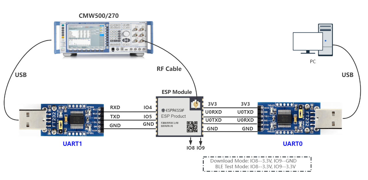
As shown in the figure above, use two USB-to-UART boards to connect UART0 and UART1 respectively. UART0 is used for serial command input and log viewing, and UART1 is used as the port for connecting tester.
PC is connected to the USB-to-UART board via USB. The PC needs to have the EspRFTestTool toolkit, tester control software, and the driver for the USB-to-UART board installed.
Tester is used to test the RF performance of the device under test (DUT) in different modes. It connects to DUT via an RF connection cable to transmit RF signals. Typically, it is CMW500, CMW270, or Bluetooth tester CBT.
USB-to-UART board is used to communicate between the computer and the DUT, as well as between the tester and the DUT.
Device under test (DUT) refers to a product designed based on the ESP32 chip or module.
Note
The DTM firmware provided by ESP uses GPIO4 and GPIO5 as the UART1 test pins by default. To change them, use the serial command on UART0.
The CHIP_EN pin of the DUT is pulled up by default. If it is not pulled up in the product design, you need to manually connect the CHIP_EN to the 3V3 pin.
Some serial communication boards have already swapped RXD and TXD internally, so there is no need to reverse the connection. Adjust the wiring according to the actual situation.
ESP32 has a power-on self-calibration feature. The RF connection cable must be connected to the tester before the DUT is powered on for testing.
Conduction Test
For modules without an onboard PCB antenna, the RF connection cable can be directly soldered to the antenna feed point of the module (as shown in the schematic diagram above).
For modules with an onboard PCB antenna, cut the trace that connects to the PCB antenna feed point and solder the RF connection cable. The RF cable’s shielding metal layer must be thoroughly soldered before connecting to the module’s GND. The GND soldering point can be either the shield cover or the exposed GND layer on the PCB (after removing the green solder mask). Besides, it should be as close to the feed point as possible.
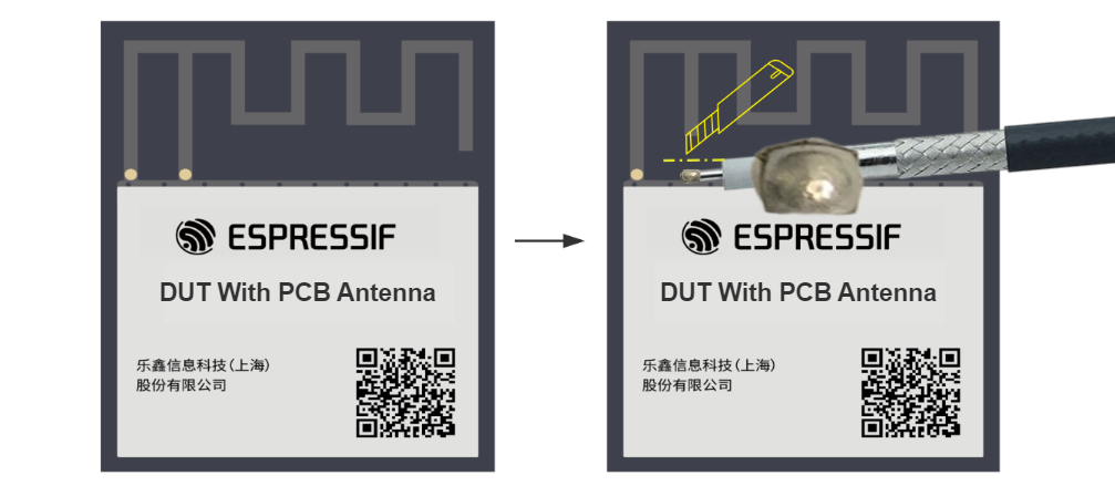
Soldering RF Connection Cable to Module with Onboard PCB Antenna
Flash Firmware
Open DownloadTool.
Set
ChipType,Com Port,Baud Rate, clickOpen, and select to download toFlash.Flash the ESP32 Bluetooth LE DTM Test Firmware bin file to the following address via
UART.
Bin File |
Flash Address |
|---|---|
0x1000 |
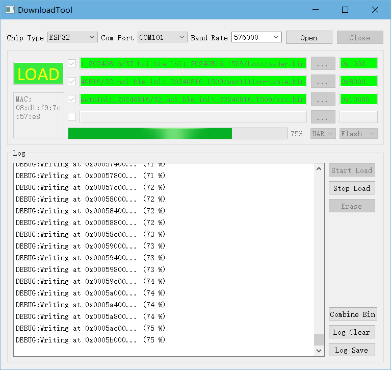
Flash Firmware
After the flash process is completed, pull up or leave the boot pin unconnected. After the chip restarts and enters the working mode, continue with the following steps for testing.
Start Testing
The connection methods between the DUT and the tester includes HCI and 2-wire, with HCI being the default option.
Based on the hardware connections described above, you can verify whether the firmware flashing was successful by checking the output from the UART0 serial port.
Upon powering on, the device defaults to a power level of 6 dBm, operates without flow control, and uses a baud rate of 115200 for initialization. No commands are required, so you can directly begin the DTM test.
Appendix
This appendix provides the mapping of power levels and target power of ESP32 for RF debugging or testing reference.
Power Level |
ESP32 Bluetooth/Bluetooth LE Transmit Power (dBm) |
0 |
-12 |
1 |
-9 |
2 |
-6 |
3 |
-3 |
4 |
0 |
5 |
3 |
6 |
6 |
7 |
9 |