Wi-Fi Adaptivity Test
The Wi-Fi Adaptivity Test evaluates a device’s ability to make real-time adjustments to parameters, such as transmission rate, channel selection, and power levels, by simulating varying network conditions and loads. This test aims to optimize the overall network performance and stability.
Note
If the power spectral density (PSD) of the Wi-Fi signal is higher than 10 dBm/MHz, the adaptivity test should choose the Listen Before Talk (LBT) mechanism based on non-hopping load.
Set Up Test Environment

UART Connection Description
The Device Under Test (DUT) is a product designed based on Espressif chips or modules. The DUT is connected to the USB-to-UART adapter board via UART.
Note
The CHIP_EN pin of the DUT is pulled up by default. If it is not pulled up in the product design, you need to manually connect the CHIP_EN to the 3V3 pin.
Some serial communication boards have already swapped RXD and TXD internally, so there is no need to reverse them. The wiring should be adjusted according to the actual situation.
Espressif chips have a power-on self-calibration function, so the RF connection line must be connected to the test instrument before the DUT is powered on for testing.
Flash Firmware
Open DownloadTool.
Set
ChipType,Com Port,Baud Rate, clickOpen, select to download toFlash.Flash ESP32 Wi-Fi Adaptivity Test/Blocking Test Firmware to 0x1000 via
UART.
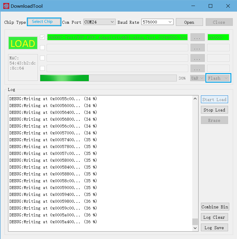
Flashing Firmware
After the flashing is completed, continue with the following steps for the adaptivity test.
Start Testing
Note
Set BaudRate to 115200.
Check Power-on log
Use a serial communication tool, such as SerialPortUtility, and configure the port number and the baud rate. If the device under test prints similar information as below after being powered on again, you can confirm that the test status is OK:
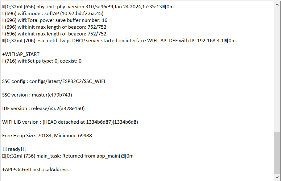
Device Power-on Serial Port Print Log
Next, you can choose to test using serial port commands or test using EspRFTestTool tool.
Test Using Serial Port Commands
Enter the following commands in the serial port in sequence for network configuration and traffic testing:
//Device provisioning
//Configure the prototype to enter station mode
op -S -o 1

//Connect to AP, SSID is CMW-AP, password is 12345678
sta -C -s CMW-AP -p 12345678

//Traffic test
//Clear socket
soc -T

//Create UDP, port is 8080, default socket ID is 54
soc -B -t UDP -p 8080

//Perform traffic test on AP device with socket ID 54
soc -S -s 54 -i 192.168.1.1 -p 8080 -l 2000 -n 200000000 -j 1
Note
The -p parameter is used to set the AP password. If the AP has no password, this parameter is not needed.
If the following similar information is printed in the serial port, it indicates that the traffic has been started and the Wi-Fi Adaptivity Test can be initiated.
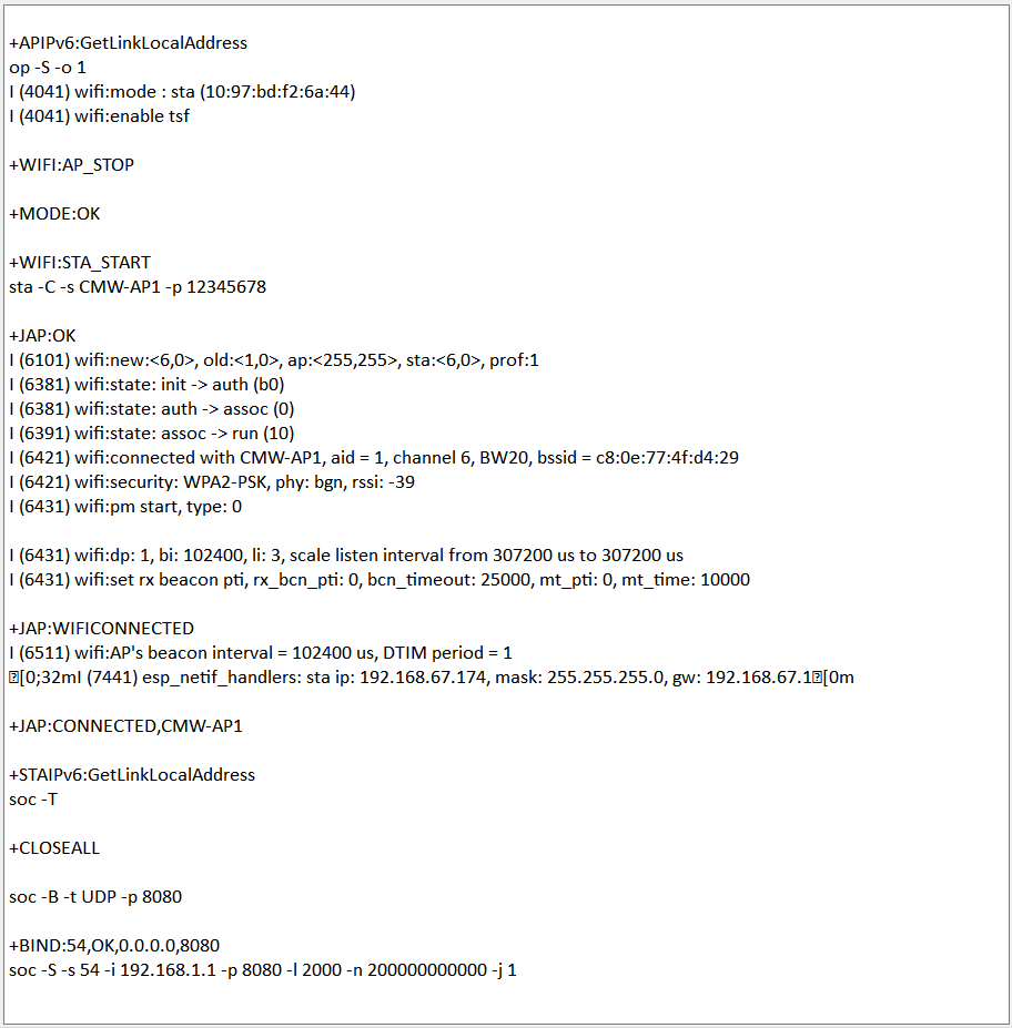
Serial Port Log for Device Provisioning
Test Using EspRFTestTool Tool
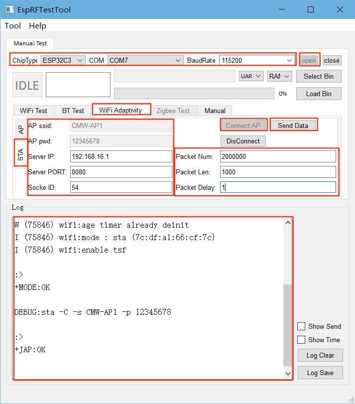
Open the EspRFTestTool toolkit, configure
ChipType,COM, andBaudRate, open the port, and select theWiFi Adaptivitytest interface.In
STAmode, enterAP ssidandAP pwd, and clickConnect APto connect.After successful connection, the following log should be printed:
Device Network Provisioning
After a successful connection, set
Packet Numto a sufficiently large value—such as 20000000—to ensure the traffic can run for a long duration.Set
Server PORTto 8080,Socket IDto 54, and changePacket Delayto 1 to meet certification requirements.After the above settings are completed, click
Send Data. If the log is similar to the figure below, it indicates that the traffic has been started, and the Wi-Fi Adaptivity Test can be initiated.
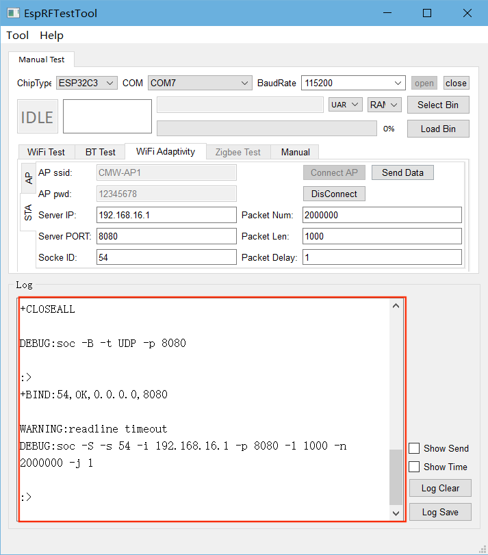
Wi-Fi Adaptivity Traffic Test