Wi-Fi Non-Signaling Test
The Wi-Fi Non-Signaling Test, also known as fixed frequency test, directly controls the device to transmit specific signals without establishing a data connection. It evaluates key RF performance metrics, such as transmit power, spectrum quality, and error rate, ensuring wireless communication quality in various scenarios.
Set Up Test Environment
The RF non-signaling test firmware environment mainly includes a PC, tester, a USB-to-UART board, a device under test (DUT), and a shield box.
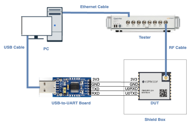
Test Environment Setup
PC is connected to the USB-to-UART board via USB and to the tester via an Ethernet cable. The PC needs to have the EspRFTestTool toolkit, tester control software, and the driver for the USB-to-UART board installed.
Tester is used to test the RF performance of the DUT in different modes. Typically, it is the WT-328/IQXel tester.
USB-to-UART board is used to communicate between the PC and the DUT.
Device under test (DUT) refers to a product designed based on the ESP32 chip or module. It is connected to the USB-to-UART board via UART and to the tester via an RF connection cable. The DUT is usually placed inside a shield box.
Shield Box is used to isolate external RF interference and ensure the stability of the test environment.
Note
The CHIP_EN pin of the DUT is pulled up by default. If it is not pulled up in the product design, you need to manually connect the CHIP_EN to the 3V3 pin.
Some serial communication boards have already swapped RXD and TXD internally, so there is no need to reverse the connection. Adjust the wiring according to the actual situation.
ESP32 has a power-on self-calibration feature. The RF connection cable must be connected to the tester before the DUT is powered on for testing.
Conduction Test
For modules without an onboard PCB antenna, the RF connection cable can be directly soldered to the antenna feed point of the module (as shown in the schematic diagram above).
For modules with an onboard PCB antenna, cut the trace that connects to the PCB antenna feed point and solder the RF connection cable. The RF cable’s shielding metal layer must be thoroughly soldered before connecting to the module’s GND. The GND soldering point can be either the shield cover or the exposed GND layer on the PCB (after removing the green solder mask). Besides, it should be as close to the feed point as possible.
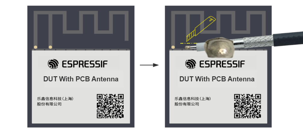
Soldering RF Connection Cable to Module with Onboard PCB Antenna
Flash Firmware
Open EspRFTestTool.
Set
ChipType,COM,BaudRate, and clickOpento open the COM port.
Note
Set BaudRate to 115200
Flash ESP32 RF Non-Signaling Test Firmware to
FlashviaUART.
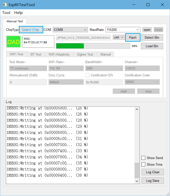
ESPRFTestTool Configuration
After the firmware flashing is completed, pull the boot pin high or leave it floating. The chip will enter the working mode after power-off restart.
Note
If you use the flash download tool to flash the firmware, change the flash address of ESP32 to 0x1000.
Start Testing
Wi-Fi TX Performance Test
Test Mode:
TX packet: Packet transmission duty cycle less than 50%, used for TX performance tests
TX continues: Packet duty cycle close to 100%, used for certification tests;
TX tone: Used for single-carrier tests.
Wi-Fi Rate: Set Wi-Fi test rate
BandWidth: Set Wi-Fi test bandwidth
Channel: Set Wi-Fi test channel
Atteunuation (0.25 dB): Set power attenuation
0 means no attenuation, which is the default value;
2 means 0.5 dB attenuation;
4 means 1 dB attenuation, and so on.
Duty Cycle: Set the packet duty cycle in TX packet tests. The default duty cycle is around 30%. Supported values: 10%, 50%, 90%.
Certification EN: Not enabled by default. Used only when verifying Power Limit function.
Certification Code: Not enabled by default. Used only when verifying Power Limit function.
After clicking start, the log window should print Wi-Fi transmission parameters similar to the following:
Wifi tx out: channel=1, rate=0x0, BK=0, length=50, delay=1200, packet_num=0
The above parameters indicate that Wi-Fi packet transmission is normal, and the transmission performance can be detected with tester at this time.
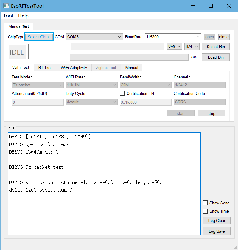
Wi-Fi TX Performance Test
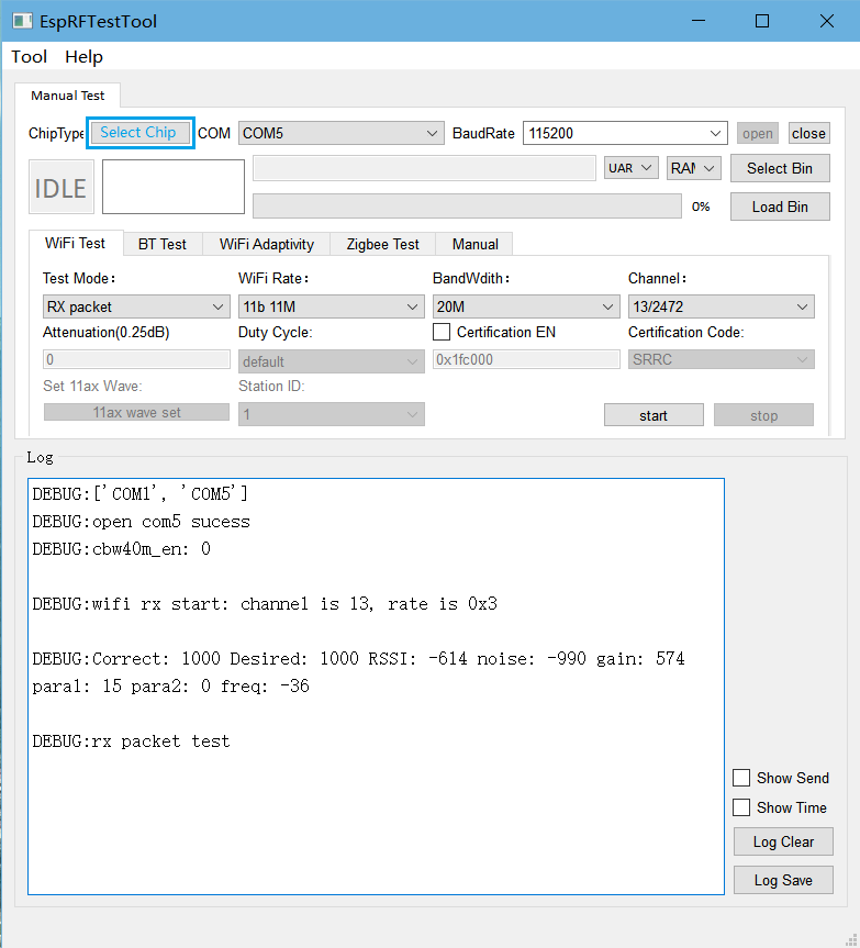
Wi-Fi RX Performance Test
Test Mode: Set to
RX packetfor RX performance tests.Wi-Fi Rate: Set Wi-Fi test rate.
BandWidth: Set Wi-Fi test bandwidth.
Channel: Set Wi-Fi test channel.
After clicking start, the tester sends packets on the test channel. Click stop after completion. The log window should display packet RX information similar to the following:
Correct:1000 Desired:1000 RSSI:-614 noise:-960 gain:0 paral:0 para2:0 freq:0
Where:
Correct: The total number of packets received this time.
Desired: The number of packets received at the corresponding rate this time.
RSSI: Represents the average RSSI of the received Desired packets. For example, “RSSI: -614” means the RSSI value is -61.4.
Note
If
Desiredis 0, no packets were received from the tester. Please check the tester’s packet settings and packet file to ensure the packet RX link is normal;If
Desiredis not 0 andCorrectis greater thanDesired, there is interference in the environment. Please retest in a shielded environment;Other parameters in the packet RX information are only used for RD debug and have no actual meaning.
Wi-Fi RX Performance Test
Appendix
This appendix is mainly used to explain the target output power of the chip’s Wi-Fi, which is used for RF debugging or test reference.
Rate |
ESP32 Wi-Fi Target Power (dBm) |
11b 1M |
19.5 |
11b 11M |
19.5 |
11g 6M |
18 |
11g 54M |
14 |
HT20-11n MCS0 |
18 |
HT20-11n MCS7 |
13 |
HT40-11n MCS0 |
18 |
HT40-11n MCS7 |
13 |