USB PHY/Transceiver Introduction
The function of the USB PHY/Transceiver is to convert the digital signals from the USB controller into USB bus signal levels, providing bus driving capability, and detecting receive errors, among other functions. Chips like ESP32-S2/S3/P4 have a built-in USB Full-speed PHY, allowing users to directly use the USB D+ D- pins specified by the chip for communication with an external USB system. Additionally, ESP32-P4 has a built-in USB High-Speed PHY. ESP32-S2/S3 retains an external PHY extension interface, allowing users to connect an external PHY when needed.
Use the internal PHY
The ESP32-S2/S3/C3 internally integrates a USB PHY, eliminating the need for an external PHY chip. It can directly connect to external USB hosts or devices through the USB D+/D- pins. However, for chips with two integrated USB controllers, such as the ESP32-S3 with built-in USB-OTG and USB-Serial-JTAG, both controllers share a single internal PHY, allowing only one to operate at a time.

The internal USB-PHY corresponds to fixed GPIO pins, as shown in the table below:
D+ |
D- |
|
|---|---|---|
ESP32-S2 |
20 |
19 |
ESP32-S3 |
20 |
19 |
ESP32-C3 |
19 |
18 |
ESP32-C6 |
13 |
12 |
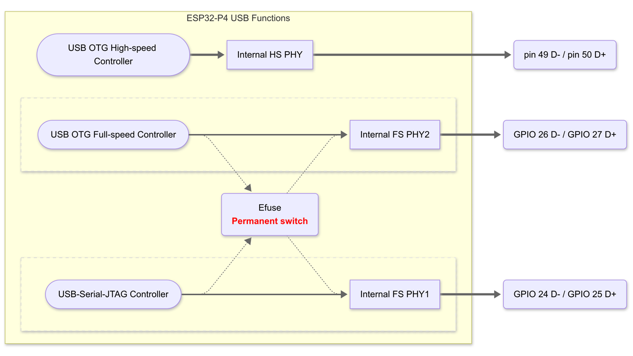
For ESP32-P4, it internally integrates two USB Full-speed PHYs and one USB High-speed PHY.

The internal USB-PHY corresponds to fixed GPIO pins, as shown in the table below:
D+ |
D- |
|
|---|---|---|
ESP32-P4 FS_PHY1 |
25 |
24 |
ESP32-P4 FS_PHY2 |
27 |
26 |
ESP32-P4 HS_PHY |
pin 50 |
pin 49 |
The default connection is FS_PHY1 connected to the USB Serial/JTAG controller, and FS_PHY2 connected to OTG_FS. The user can change the connection relationship through EFUSE_USB_PHY_SEL.
Use an external PHY (ESP32-S2/S3)
By adding an external PHY, it is possible to enable the simultaneous operation of both USB-OTG and USB-Serial-JTAG.
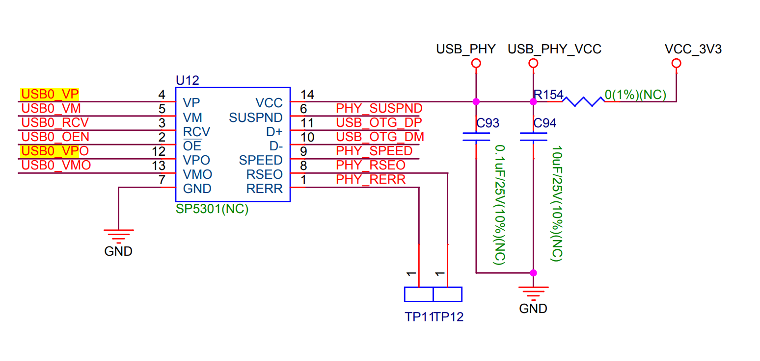
ESP32S2/S3 supports SP5301 or equivalent USB PHY. A typical circuit diagram for an external PHY is as follows:

Using an external USB PHY will occupy a minimum of 6 GPIO pins.
USB PHY default configuration
For chips that feature both USB-OTG and USB-Serial-JTAG peripherals simultaneously, the default configuration is for USB-Serial-JTAG to be connected to the internal USB-PHY. Users can directly download or debug through the USB interface without additional configuration.
If there is a need to develop a USB-OTG application using USB Host Driver or the TinyUSB protocol stack, during protocol stack initialization, the USB-PHY connection will automatically switch to USB-OTG, and users do not need to perform additional configuration. In USB-OTG mode, if users wish to utilize the download functionality of USB-Serial-JTAG, they need to manually boot into download mode.
Modify the default configuration of the USB PHY
Method 1: Switch the USB-PHY connection to USB-OTG by configuring the registers.
The USB Host Driver or TinyUSB stack internally switches the connection of the internal USB-PHY to USB-OTG by configuring USB PHY registers. For more information, please refer to the USB PHY Configuration API.
Method 2: Switch the default connection of USB-PHY to USB-OTG by burning the efuse usb_phy_sel bit to 1.
This efuse bit should only be burned if the user needs to use USB-OTG functionality in Boot mode. Once burned, when the chip enters Boot mode, it will utilize the download functionality provided by USB-OTG, such as USB DFU.
Note that once the efuse bit is burned to 1, it cannot be restored to 0. When the USB-PHY default connection is switched to USB-OTG, and the chip enters Boot mode, USB-OTG functionality will be active, and USB-Serial-JTAG functionality will be unavailable.
Note: For ESP32-S3 modules and development boards produced before DateCode 2219 (PW No. earlier than PW-2022-06-XXXX), because EFUSE_DIS_USB_OTG_DOWNLOAD_MODE (BLK0 B19[7]) has already been burned to 1 (USB OTG download disabled), if users burn the efuse_usb_phy_sel bit to 1, it will result in both USB-Serial-JTAG and USB-OTG download functionalities being disabled when the chip enters Boot mode.