Using WSL in Windows
This tutorial guides you on developing projects using Visual Studio Code with ESP-IDF extension and Remote - WSL to implement all features of these extensions in WSL.
Install the following tools before starting the project:
Windows WSL (see installation steps below)
Installing Ubuntu on Windows (WSL)
To install WSL, run:
wsl --install
Update the WSL kernel with:
wsl --update
Check the available WSL distributions using the Powershell command prompt:
wsl -l -o
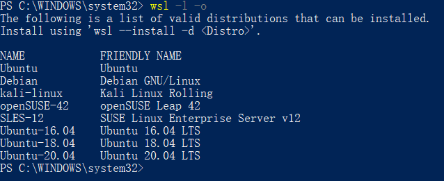
To install a Ubuntu distribution in WSL on Windows, type the following command:
wsl --install --distribution Ubuntu
usbipd-win in WSL
To access USB, serial, and JTAG devices from the local Windows system, you must install usbipd-win. Without it, downloading, monitoring, and debugging on the IDF Docker image is not possible. The installation process is similar to other Windows applications and will not be detailed here.
After installing all the required tools, configure WSL as follows:
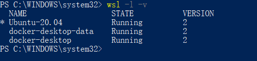
Check Ubuntu on Windows (WSL)
Verify that the current WSL version is 2.
wsl -l -v
If the version is not 2, upgrade to version 2.
wsl --set-version Ubuntu 2
Set the Ubuntu distribution as the default.
wsl -s Ubuntu
Confirm the settings using the
wsl --statuscommand.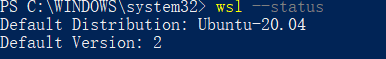
Adding the Required Linux Packages in WSL
Install ESP-IDF Requirements for Linux.
sudo apt-get install git wget flex bison gperf python3-pip python3-venv python3-setuptools cmake ninja-build ccache libffi-dev libssl-dev dfu-util
Install
usbipdin the Powershell command prompt:winget install usbipd
Configure the USB serial device to connect to WSL using
usbipd.Open the PowerShell command prompt with administrator rights and then enter the following command to get a list of USB serial devices.
usbipd list
To access a specified device from Windows on WSL locally, bind the device with
usbipd. Open the PowerShell command prompt with administrator rights and enter the following command.usbipd bind --busid <BUSID>
Note
Use this command only once unless the computer restarts. 1-1 is the device’s
<BUSID>you want to bind.After binding, attach the specified device to WSL with the following command in the PowerShell command prompt.
usbipd attach --wsl --busid <BUSID>
Finally, verify the connection on the WSL side by entering the following command.
dmesg | tail
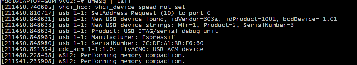
As shown above, the 1-1 device is attached to ttyACM0, indicating that WSL can now access the 1-1 USB device.
Install Remote WSL Extension in Visual Studio Code
Install the Remote - WSL, Remote Development and ESP-IDF extensions as shown below.

Open Project in WSL
Start your development by clicking the >< button at the bottom left of Visual Studio Code. Select Open Folder in WSL to configure the WSL and open the Blink example project.
Configure the ESP-IDF extension inside WSL as described in Install ESP-IDF and Tools.
Note
Running the setup from WSL could override the Windows host machine configuration settings since it uses User Settings by default. Consider saving settings to a workspace or workspace folder.
Note
When EIM is launched in WSL using CLI wizard mode, the extension also adds the EIM executable directory to the WSL user’s shell PATH. Open a new WSL terminal afterwards to run eim directly, and refer to the EIM CLI Commands page for supported commands.
You can now use the Blink example project for building, flashing, monitoring, debugging, etc.
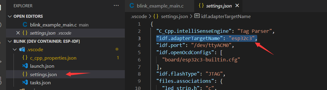
Building Your Project
For example, to use ESP32-C3, change the target device from esp32 to esp32c3 as shown below:
Next, start building the example project:
Flashing to your Device
After building, flash the firmware using one of the following methods.
External USB-to-Serial
Follow the usbipd instructions as described. Here, Silicon Labs CP210x USB to UART Bridge is used as an example and is attached to the Docker image.
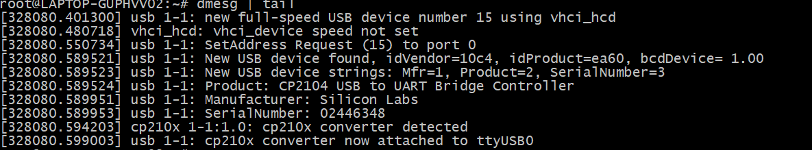
This device is attached to ttyUSB0, so you need to update idf.port accordingly.
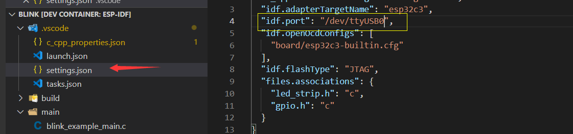
The container does not recognize the configuration change immediately.
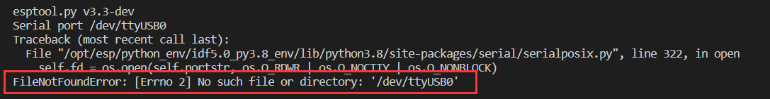
Reopen the container by selecting Reopen Folder Locally to reload the new configuration.
Finally, click the Flash button to download the firmware.
Internal USB-to-Serial
Similar to External USB-to-Serial, the only difference is the device name attached, where the external USB-to-Serial is ttyUSBx, while the internal USB-to-Serial is ttyACMx.
USB-to-JTAG
Same as External USB-to-Serial and Internal USB-to-Serial, but it needs to configure the following extra parameters:
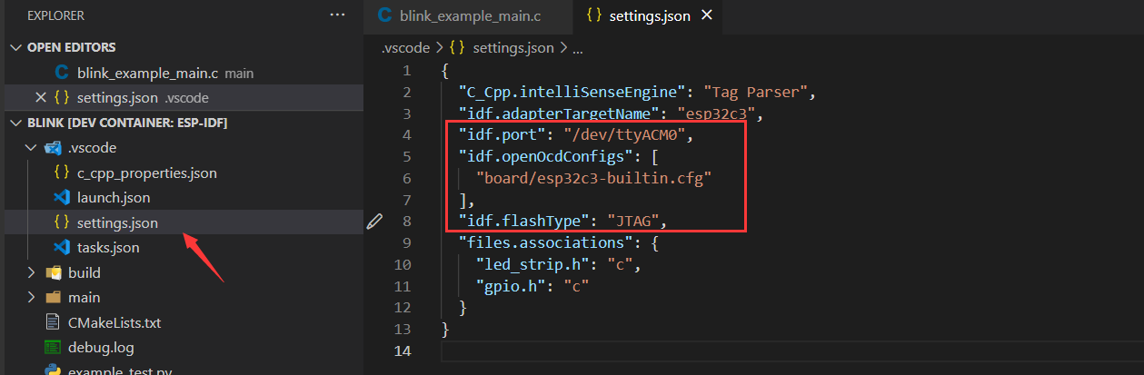
The interface is the same as Internal USB-to-Serial, which is ttyACMx:

Additional Steps for Debugging
Copy OpenOCD udev rules files and paste them to the /etc/udev/rules.d directory before running OpenOCD and starting a debug session.
Precautions
To debug on Windows, unplug and re-plug the USB cable to ensure the USB port is recognized in the Windows Device Manager.
Keep Docker Desktop for Windows open during container development.